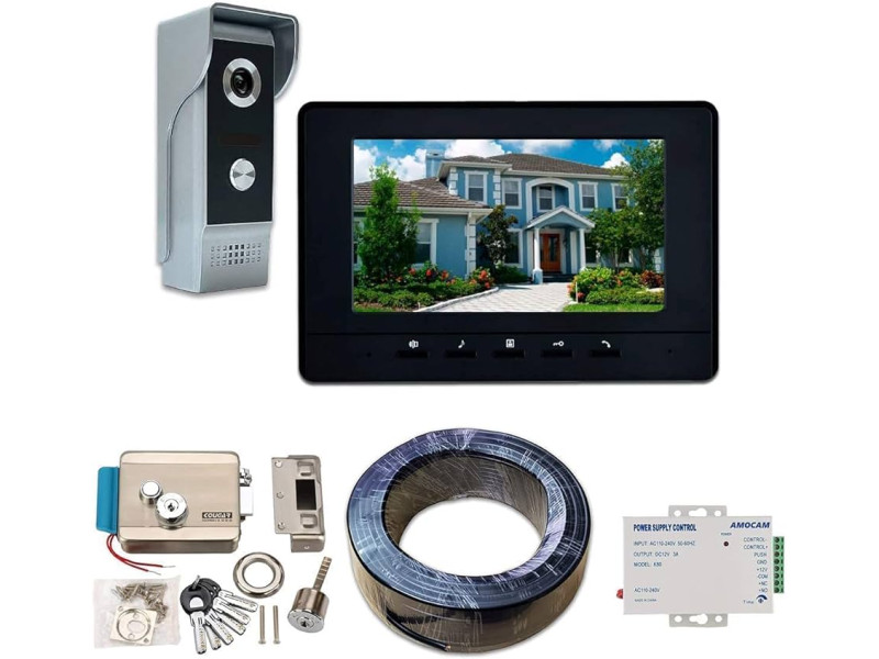
Electromechanical Locks are integral components of modern video intercom systems, providing robust security and seamless access control for both residential and commercial properties. Properly connecting these locks to your video intercom ensures reliable operation and enhances the overall security of your premises. This guide explores the various connection schemes for electromechanical locks, including setups with and without a separate power supply, installation considerations for homes and apartments, and practical tips to help you achieve a secure and efficient intercom system setup.
Connection Schemes for Electromechanical Locks
Connecting an Electromechanical Lock (EML) to a video intercom system can be accomplished through different methods. The two primary schemes are:
- Using a Power Supply Block
- Using a Control Unit (BUZ) Without a Power Supply Block
1. Connection Scheme Using a Power Supply Block
Overview: When connecting an electromechanical lock with a power supply block, the system relies on an external power source to handle the significant current required for unlocking. This method is straightforward and ensures that the lock receives the necessary power without overloading the intercom panel.
Steps:
Select a Suitable Power Supply:
- Voltage Requirements: Typically 12V or 24V DC, depending on the lock specifications.
- Current Capacity: Ensure the power supply can handle the lock’s current draw (usually several amperes).
Wiring the Lock:
- Power Lines: Use high-gauge cables (0.75mm² to 1.5mm²) to connect the power supply block to the electromechanical lock, minimizing voltage drop over long distances.
- Control Lines: Connect the intercom panel’s relay to the lock, ensuring the relay can handle the lock’s current.
Relay Configuration:
- Normally Open Contacts: The intercom panel should have relay contacts that close to send a brief electrical pulse to unlock the door.
- Ensure Compatibility: Verify that the intercom’s relay is rated for the lock’s current requirements.
Integration with Access Control:
- Optional Controllers: If using electronic keys (e.g., Touch Memory or Proximity cards), integrate a controller that manages the access codes and interacts with the intercom system.
Testing:
- Verify Operation: Press the intercom’s unlock button and ensure the lock responds with a smooth, brief unlocking pulse.
- Check for Overheating: Ensure the lock does not overheat during operation, indicating proper power handling.
Considerations:
- Cable Length: For long runs (e.g., from the power supply to a gate), use cables with larger cross-sectional areas to prevent voltage drops.
- Relay Rating: Confirm that the intercom panel’s relay can handle the current drawn by the electromechanical lock.
2. Connection Scheme Without a Power Supply Block (Using BUZ)
Overview: This method involves using a Block of Control for Locks (BUZ), which eliminates the need for a separate power supply by utilizing a large-capacity electrolytic capacitor to store and deliver the necessary power for unlocking. This simplifies installation but has certain limitations, especially in environments with extreme temperatures.
Steps:
Install the BUZ:
- Location: Mount the BUZ close to the electromechanical lock to minimize power loss and ensure efficient operation.
- Protection: Place the BUZ in a sheltered area to protect it from environmental factors, especially if installed outdoors.
Wiring the BUZ:
- Power Connection: Connect the BUZ to the intercom panel using a two-conductor cable with a minimum cross-section of 1.5mm².
- Lock Connection: Attach the BUZ to the electromechanical lock, ensuring secure and proper connections.
Operational Principle:
- Charging Phase: The BUZ slowly charges from the intercom panel’s power supply.
- Unlocking Pulse: When the unlock command is received, the BUZ discharges rapidly to provide the necessary current for the lock’s solenoid, retracting the latch.
Integration with Access Control:
- Electronic Key Compatibility: Similar to the power supply scheme, integrate controllers if electronic access methods are used.
Testing:
- Verify Unlocking: Activate the intercom’s unlock function and ensure the BUZ delivers a sufficient pulse to operate the lock.
- Monitor Temperature Sensitivity: Ensure the BUZ operates correctly in the expected temperature range, as extreme cold can affect capacitor performance.
Considerations:
- Temperature Sensitivity: In environments with significant temperature fluctuations, the BUZ’s performance may be compromised, potentially leading to capacitor failure.
- Current Handling: The BUZ must be capable of delivering the required current without overloading, which may necessitate using a BUZ with built-in protections.
Installation for Homes and Apartments
A. Installation in Private Homes
Typical Setup:
- Primary Locations: Entrance door, gate, and possibly backyard or side doors.
- Lock Integration: Preferably using electromechanical locks for their reliability and manual override capabilities.
- Additional Cameras: Optional cameras for broader surveillance coverage.
Steps:
Mount the External Call Panel:
- Height: Install at an optimal height (140-150 cm or 55-59 inches) for easy access and camera visibility.
- Positioning: Ensure the camera has an unobstructed view of the entrance.
Install the Monitor:
- Location: Central indoor area for easy access and visibility.
- Mounting: Securely attach to the wall at a comfortable viewing height (4-5 feet from the floor).
Connect the Lock:
- Choose Connection Scheme: Decide between using a power supply block or BUZ based on your installation environment and lock type.
- Wiring: Follow the selected connection scheme, ensuring secure and proper wiring.
Test the System:
- Functionality Check: Ensure the intercom communicates effectively with the lock, allowing for smooth unlocking.
- Troubleshoot Issues: Address any connectivity or power issues before finalizing the installation.
B. Installation in Apartments
Typical Setup:
- Primary Locations: Shared entrances, multiple individual apartment doors.
- Lock Integration: Often use electromagnetic locks for shared entrances; individual apartments may have their own electromechanical locks.
- Centralized Management: Utilize switchboards or controllers to manage multiple intercom panels and locks.
Steps:
Coordinate with Neighbors:
- System Compatibility: Ensure all units use compatible intercom components for seamless integration.
- Common Features: Agree on common system features and access control methods.
Mount External Call Panels:
- Placement: Install at each entry point, ensuring secure and accessible placement.
- Height: Maintain the optimal height (140-150 cm) for all panels.
Install Monitors:
- Location: Inside each apartment, ensuring they are connected to their respective external panels.
- Mounting: Securely attach monitors in easily accessible locations.
Connect Locks:
- Use Controllers: Implement controllers to manage multiple locks efficiently, ensuring synchronized operation.
- Wiring: Follow the connection schemes, ensuring that each lock is correctly wired and powered.
Test the System:
- Comprehensive Testing: Verify communication and lock functionality across all units to ensure consistent performance.
Practical Tips for Successful Installation
1. Professional Installation vs. DIY
Professional Installation:
- Advantages: Ensures precise alignment, secure mounting, and proper wiring. Ideal for complex systems or high-security requirements.
- Considerations: Involves additional costs but guarantees reliable and compliant setup.
DIY Installation:
- Advantages: Cost-effective and allows for personal customization.
- Considerations: Requires careful planning, adherence to wiring standards, and thorough testing to avoid operational issues.
2. Choosing the Right Equipment
- Compatibility: Select components from the same manufacturer to ensure seamless integration and reduce compatibility issues.
- Quality: Opt for high-quality cables and connectors to prevent signal loss and ensure long-term reliability.
- Future Expansion: Consider systems that allow for easy addition of components like extra cameras or monitors.
3. Ensuring Proper Wiring Practices
- Cable Management: Use conduits or cable clips to route cables neatly and protect them from physical damage.
- Wire Gauge: Use appropriate wire gauges to handle the current requirements of your locks, especially for electromechanical locks that draw higher currents.
- Testing: Test all connections before finalizing the installation to ensure signal integrity and power delivery.
4. Power Supply Considerations
- Dedicated Power Sources: For high-current locks, use dedicated power supplies to prevent overloading the intercom panel.
- Backup Power: Implement Uninterruptible Power Supplies (UPS) or battery backups to maintain system functionality during power outages.
5. Compliance and Safety
- Electrical Codes: Adhere to the National Electrical Code (NEC) and other relevant standards to ensure safe and compliant installations.
- Weatherproofing: For outdoor components, ensure they are rated for weather resistance (e.g., IP67) to protect against environmental elements.
- Secure Mounting: Use tamper-proof hardware to prevent unauthorized access or removal of components.
Frequently Asked Questions
1. How to Connect an Electromechanical Lock to a Video Intercom System?
Answer: Connecting an electromechanical lock involves selecting the appropriate connection scheme (with a power supply block or using BUZ), ensuring compatibility between the intercom panel and the lock, and using proper wiring techniques. Follow the detailed connection steps outlined in this guide to ensure a secure and functional setup.
2. What is the Optimal Height for Mounting the External Call Panel?
Answer: The external call panel should be mounted at a height between 140 to 150 cm (55 to 59 inches) from the ground. This placement ensures that:
- Ease of Access: Users of all ages can comfortably reach and press the call button.
- Optimal Camera View: The visitor’s face is well-positioned within the camera’s field of view for clear identification.
3. What Type of Cable is Required for Connecting an Electromechanical Lock?
Answer: The type of cable depends on the connection scheme and distance:
- For Power Supply Block Scheme: Use high-gauge cables (0.75mm² to 1.5mm²) to handle the current draw (typically 3A or higher).
- For BUZ Scheme: Use a two-conductor cable with a minimum cross-section of 1.5mm².
- For Long Distances: Consider using 75-ohm coaxial cables (e.g., RG-6, RG-59) to minimize signal loss and interference.
Key Considerations:
- Wire Gauge: Ensure the wire gauge is sufficient to handle the lock’s current without significant voltage drops.
- Quality: Use durable, copper-based cables with proper shielding to prevent signal interference and ensure reliable operation.
4. Do I Need a Separate Power Supply for My Electromechanical Lock?
Answer: Yes, for most setups, especially when using the power supply block connection scheme, a separate power supply is necessary to handle the high current demands of electromechanical locks. This prevents overloading the intercom panel and ensures stable and reliable lock operation.
5. What Should I Do If My Intercom Panel’s Relay Cannot Handle the Lock’s Current?
Answer: If the intercom panel’s relay is not rated to handle the lock’s current, you should:
- Use a Relay Adapter: Install an external relay that can handle the higher current and interface it with the intercom panel’s control signal.
- Upgrade the Intercom Panel: Consider upgrading to an intercom system that supports higher current ratings for relays.
- Consult a Professional: Seek assistance from a certified electrician or security professional to ensure safe and compliant modifications.
Final Thoughts
Connecting Electromechanical Locks to Video Intercom Systems is a crucial step in establishing a secure and efficient access control setup for your home or apartment. By understanding the different connection schemes, adhering to best installation practices, and selecting compatible and high-quality components, you can ensure a reliable and robust security system. Whether opting for a power supply block scheme or using a BUZ, careful planning and execution are essential to achieve optimal performance and security.
Key Takeaways:
Understand Connection Schemes: Familiarize yourself with both connection schemes-using a power supply block and using a BUZ-to choose the best fit for your installation environment.
Ensure Compatibility: Select intercom and lock components that are compatible, preferably from the same manufacturer, to facilitate seamless integration.
Use Proper Wiring: Employ high-quality, appropriately gauged cables to handle the lock’s current requirements and prevent signal loss or overheating.
Implement Backup Power: Incorporate UPS or battery backups to maintain system functionality during power outages, ensuring continuous security.
Adhere to Standards: Follow the National Electrical Code (NEC) and other relevant standards to ensure safe and compliant installations.
Consider Professional Installation: For complex setups or high-security requirements, consider hiring certified security professionals to ensure precise and secure installation.
Regular Maintenance: Conduct routine inspections and maintenance to ensure all components function correctly and to prevent wear-related issues.
Secure Mounting Practices: Use tamper-proof hardware and mount components securely to prevent unauthorized access or tampering.
Plan for Future Expansion: Choose systems that allow for easy addition of components like extra cameras or additional locks as your security needs evolve.
Choose Reputable Brands: Opt for electromechanical locks from well-known manufacturers like CISA, ATIS, and POLIS to ensure quality, reliability, and comprehensive support.
For expert assistance in connecting electromechanical locks to video intercom systems, ensuring compliance with relevant standards, or accessing comprehensive project documentation, visit safsale.com. Our specialists are ready to help you design and deploy reliable, compliant, and efficient access control solutions tailored to your specific security needs.
Important Notice on Standards
All referenced documents and standards in this guide are provided for informational purposes only and should not be used as official publications. For authoritative guidelines and legal requirements, always consult the official standards organizations or regulatory bodies.