How to Test a Diode Bridge with a Multimeter: Step-by-Step
A diode bridge (bridge rectifier) is a configuration of four diodes arranged to convert AC to DC. Testing a diode bridge ensures it is functioning correctly by verifying each diode’s conduction in the forward direction and blocking in reverse.
⚠ Important: To get accurate results, desolder or remove the bridge from the circuit, as other components can skew the readings.
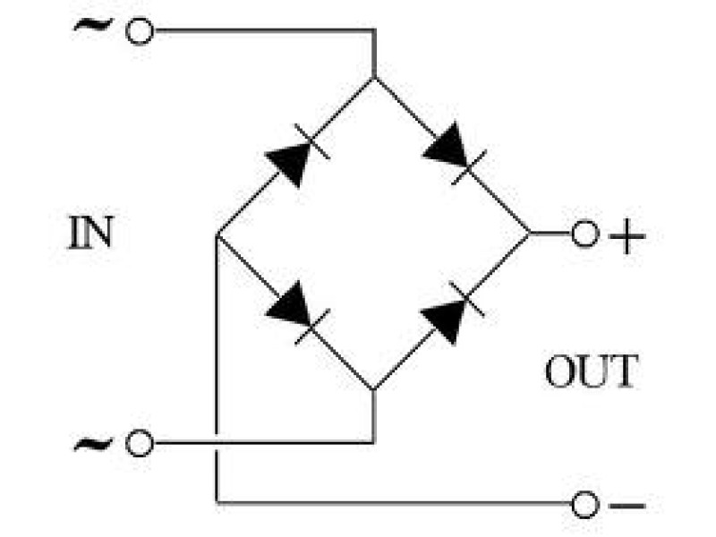
1️⃣ Understanding the Diode Bridge
A four-diode bridge has:
- Two AC input terminals (for the AC supply)
- + output terminal
- - output terminal
Each internal diode must be tested for forward conduction and reverse blocking.
Common Pinout (Reference)
2️⃣ Required Tools
- Digital multimeter (with diode test or resistance mode)
- Soldering iron (if removing the bridge from PCB)
- Test probes
3️⃣ Testing a Known-Pin Bridge
If you already know the pin assignment (marked on the module or datasheet), checking is straightforward:
Step 1: Check Each Diode in Forward Direction
- Select the diode test mode (or a high-resistance range if not available).
- Place the red probe on the diode’s anode and the black probe on the cathode.
- Read the display:
- A typical forward voltage drop () indicates a good diode.
- If the meter shows OL, 1, or infinite resistance, the diode may be open.
Step 2: Reverse the Probes
- Switch probe polarity (red probe on the cathode, black probe on the anode).
- The meter should now show OL or no conduction.
- If it shows a voltage drop, the diode is shorted (faulty).
Step 3: Repeat for All Four Diodes
Make sure each of the four internal diodes passes forward current in one direction only and blocks in the other.
4️⃣ Testing an Unknown-Pin Bridge
If the pin assignments are unknown:
Step 1: Identify the AC Input Pins
- Check pairs of pins with both polarities of the multimeter.
- AC pins will show open (OL) in both directions because in the bridge, two diodes are in series (opposing directions) at those points.
Step 2: Find + and - Outputs
- Once AC pins are located, test the other two pins.
- Typically, one pin will always conduct from each AC pin in one direction → This is the (+) output.
- The other pin will conduct to the AC pins in the opposite direction → This is the (-) output.
📌 Note: If you find a diode is shorted or open, the bridge is faulty.
5️⃣ Results Interpretation
- Forward conduction (~0.5-0.7V) → Diode is good.
- No conduction in both directions → Diode is open (faulty).
- Conduction in both directions → Diode is shorted (faulty).
- AC pins should show open in both polarities.
6️⃣ Common Faults & Symptoms
- Open Diode - The rectifier fails to provide DC output or reduced voltage.
- Shorted Diode - Typically blows fuses or triggers overcurrent protection.
- Leakage in Reverse - May cause low DC output or heat issues.
7️⃣ Practical Tips & Safety
- Desolder or remove the bridge rectifier before testing.
- Use diode test mode for best results.
- If testing in resistance mode, choose high-resistance range.
- Always ensure the circuit is unpowered and capacitors are discharged before touching any component.
8️⃣ Conclusion
Testing a diode bridge with a multimeter ensures each diode is functioning (forward conduction, reverse blocking). Key steps include:
✔ Identifying AC input and DC output pins.
✔ Checking forward and reverse conduction for each internal diode.
✔ Verifying OL or no conduction in reverse.
A faulty bridge rectifier can cause low DC output, blown fuses, or overcurrent issues-making regular testing essential in power supplies and other AC-to-DC circuits.