Grounding Systems: TN, TT, and IT Schemes and Applications
Grounding is one of the most crucial technical measures for ensuring electrical safety in power installations.
The purpose of grounding is to connect non-live metal parts of electrical equipment to grounding devices, preventing electric shock hazards for humans and animals.
In three-phase AC networks up to 1 kV, different grounding systems are used based on the neutral configuration and the handling of protective (PE) and neutral (N) conductors.
- TN Systems - Feature a solidly grounded transformer neutral.
- TT System - Uses a locally installed ground electrode for protective grounding.
- IT System - Has an isolated or resistance-grounded neutral to limit fault currents.
TN Grounding System: Types and Configurations
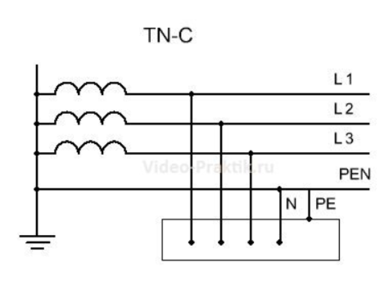
1. TN-C System
The TN-C (Terra Neutral Combined) system has a solidly grounded transformer neutral at the substation.
- Power is delivered via a four-wire system (three-phase conductors + a combined PEN conductor).
- PEN serves as both the neutral (N) and protective earth (PE) conductor.
- No additional grounding electrodes are required on the consumer’s side.
Identifying a TN-C System in a Home
- Three-phase connections use a four-wire setup.
- Single-phase connections use only two wires.
- Older homes have two-prong outlets with no grounding contacts.
Disadvantages of TN-C
- High risk of electric shock - If the PEN conductor is damaged, appliance casings may become live.
- GFCIs (Ground Fault Circuit Interrupters) do not work properly in this system.
Upgrading from TN-C
- Transition to TN-S requires installing a dedicated PE conductor from the substation.
- A simpler alternative is TN-C-S, which involves splitting PEN into PE and N before the electrical panel.
- Installing a GFCI or a circuit breaker with built-in ground fault protection can enhance safety.
2. TN-C-S System
The TN-C-S (Terra Neutral Combined-Separated) system is a hybrid solution.
- Initially, power is distributed via a TN-C (four-wire) system.
- Just before entering the building, the PEN conductor is split into separate PE (ground) and N (neutral) wires.
- The internal electrical distribution uses five wires (three-phase + N + PE).
Advantages of TN-C-S
- Provides basic ground fault protection.
- Allows the use of GFCIs (RCDs), which can trip when leakage currents are detected.
Disadvantages of TN-C-S
- PEN conductor is vulnerable to damage before the split, which can cause dangerous voltage surges.
- Additional grounding electrodes are required at regular intervals (100-200 meters) to maintain safety.
3. TN-S System
The TN-S (Terra Neutral Separated) system provides the highest level of safety.
- The PE and N conductors are completely separate from the substation to the consumer.
- The system uses a dedicated PE conductor throughout the power line, ensuring reliable grounding.
Benefits of TN-S
✅ Reliable grounding reduces electrical shock risks.
✅ No risk of losing ground protection due to PEN conductor failure.
✅ Better protection against voltage surges and faults.
Challenges of TN-S
- Expensive to implement due to the need for additional wiring.
- Difficult to retrofit in existing TN-C networks.
TT and IT Grounding Systems
1. TT Grounding System
The TT system (Terra-Terra) is used when a dedicated protective ground is required at the consumer’s location.
- The PEN conductor is grounded at the substation, but consumers must install their own ground electrode.
- The local PE conductor is isolated from the supply neutral (N).
When Is TT Grounding Used?
- In metallic buildings where the structure itself poses grounding risks.
- In areas where TN systems are impractical due to soil conditions.
- In older buildings that lack dedicated grounding conductors.
Safety Considerations in TT Systems
GFCIs (RCDs) are mandatory with a trip current of ≤30mA.
The grounding resistance (Rz) must be low enough to ensure proper fault protection:
Rz × I_GFCI ≤ 50V
Where:
- Rz = total ground resistance
- I_GFCI = residual current trip threshold
This formula ensures that touch voltage never exceeds 50V, reducing electrocution risks.
2. IT Grounding System
The IT (Isolated-Terra) system differs significantly from TN and TT systems.
- The transformer neutral is either completely isolated or connected through a high resistance.
- No protective earth (PE) conductor is supplied from the substation.
- Consumers must use a local grounding system for safety.
Where Is IT Grounding Used?
- Industrial plants, chemical plants, and oil refineries where equipment safety is critical.
- Hospitals - IT reduces the risk of ground faults affecting medical equipment.
- Explosive environments - IT grounding limits short-circuit currents, preventing sparks.
Advantages of IT Grounding
✅ Minimal fault currents prevent electrical fires.
✅ Systems can continue operating after the first ground fault.
✅ Ideal for high-risk environments.
Challenges of IT Grounding
- Complex and expensive to install.
- Requires regular insulation resistance monitoring to detect ground faults.
- Not suitable for standard residential buildings.
Comparison Table: TN, TT, and IT Systems
| Feature | TN-C | TN-C-S | TN-S | TT | IT |
|---|---|---|---|---|---|
| Separate N and PE | ❌ | ✅ (after split) | ✅ | ✅ | ✅ |
| Requires local ground? | ❌ | Optional | Optional | ✅ | ✅ |
| Supports GFCIs? | ❌ | ✅ | ✅ | ✅ | ✅ |
| Common in homes? | ✅ (old) | ✅ | ✅ | ❌ | ❌ |
| Industrial use? | ❌ | ✅ | ✅ | ✅ | ✅ |
| Best fault protection | ❌ | ✅ | ✅ | ✅ | ✅ |
| Cost to install | Low | Medium | High | High | Very High |
Conclusion: Choosing the Right Grounding System
- TN-S is the safest system but is costly to implement.
- TN-C-S is a good compromise for improving safety in older TN-C installations.
- TT is useful when a separate ground electrode is necessary.
- IT is ideal for critical infrastructure and industrial settings.
For residential and commercial buildings, TN-C-S or TN-S are the best options for ensuring safety and electrical reliability.
If upgrading from TN-C, consult a licensed electrician to transition to a safer grounding system!