What Is Grounding and Why Is It Essential?
Grounding is a critical safety system that connects electrical equipment and structures to the earth to prevent electric shock, protect equipment, and ensure stable operation.
Why is proper grounding necessary?
✔ Prevents electric shocks - Redirects dangerous currents safely into the ground.
✔ Protects electrical equipment - Reduces damage from power surges and lightning.
✔ Ensures circuit breakers function properly - Detects faults and disconnects power.
✔ Stabilizes voltage levels - Reduces electromagnetic interference and improves performance.
In private homes, commercial buildings, and industrial facilities, proper grounding ensures long-term safety and electrical system stability.
Types of Grounding Systems
Grounding systems can be classified into different types based on the installation method and specific requirements.
1. Grounding Loop (Ring Grounding System)
✔ Forms a closed-loop using metal rods or plates buried around the building.
✔ Ideal for large homes or industrial facilities.
✔ Distributes electrical currents evenly in the ground.
✔ Pros:
• High efficiency in all soil types.
• Ideal for high-power systems requiring robust grounding.
Cons:
• Labor-intensive installation due to extensive trenching.
• Higher material costs compared to simpler systems.
2. Vertical (Rod) Grounding
✔ Uses metal rods driven vertically into the ground.
✔ Effective in deep soil layers with high moisture content.
✔ Pros:
• Simple and cost-effective for residential applications.
• Good for areas with limited space.
Cons:
• Ineffective in dry or rocky soil with high resistance.
• Requires special equipment to drive rods deep enough.
3. Horizontal Grounding
✔ Flat metal strips or conductors laid horizontally underground.
✔ Best for moist or conductive soil conditions.
✔ Pros:
• Easy to install in soft soils.
• Provides good electrical contact over large areas.
Cons:
• Requires more land area compared to vertical grounding.
• Not ideal for dry, rocky, or sandy soil conditions.
How to Install Grounding: Step-by-Step Guide
1. Site Selection and Soil Assessment
Before starting, evaluate the soil type and moisture level on your property.
Best soil types for grounding:
✔ Clay and loamy soils - Best conductivity
✔ Moist soils - Lower resistance
Challenging soil conditions:
❌ Sandy or rocky soil - Requires deeper grounding electrodes
❌ Dry soil - May need soil conditioning additives
How to choose the best location?
✔ Close to the main electrical panel for shorter conductor runs.
✔ Away from underground pipes or gas lines.
✔ Avoid dry, rocky areas with poor conductivity.
2. Calculating Grounding Resistance
For proper grounding, resistance must meet national electrical codes.
Formula for calculating grounding resistance:
R=2πLρ×ln(d4L)Where:
✔ R = Grounding resistance (Ohms)
✔ ρ = Soil resistivity (Ohm-meters)
✔ L = Electrode length (meters)
✔ d = Electrode diameter (meters)
Standard resistance requirements:
✔ Home grounding: Less than 30 ohms
✔ Industrial grounding: Less than 10 ohms
✔ High-risk areas: Less than 4 ohms
3. Choosing Grounding Materials and Tools
✔ Grounding Rods:
• Copper-clad steel (best for conductivity and corrosion resistance).
• Galvanized steel rods (cheaper but less durable).
✔ Connecting Conductors:
• Copper or aluminum wires (with proper thickness).
• Welded or bolted connections (to prevent resistance increases).
✔ Tools Required:
• Shovel (for trenching).
• Hammer drill or driving rod tool (to install deep grounding electrodes).
• Multimeter or ground resistance tester (for verification).
4. Installing the Grounding System
A. Installing Vertical (Rod) Grounding
✔ Drive ground rods at least 8 feet deep into the ground.
✔ Space multiple rods at least 6 feet apart for better dissipation.
✔ Connect rods using copper grounding wire and ground clamps.
B. Installing a Grounding Loop (Ring Grounding)
✔ Dig a trench around the building (depth: 2-3 feet).
✔ Place copper strips or steel rods in the trench.
✔ Weld or clamp connections securely to ensure a low-resistance circuit.
C. Connecting the Grounding System to the Electrical Panel
✔ Route a thick copper wire from the grounding system to the main grounding busbar inside the breaker panel.
✔ Use proper grounding clamps and ensure a tight, corrosion-resistant connection.
✔ Verify all connections using a ground resistance tester.
Testing and Maintenance of Grounding Systems
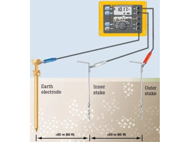
1. How to Test Grounding Resistance
✔ Use a ground resistance tester to measure ohms.
✔ Ideal grounding resistance: ≤30Ω for residential, ≤10Ω for commercial buildings.
Testing Method:
✔ Disconnect the ground wire from the panel.
✔ Connect the tester probes to the grounding rod and reference electrode.
✔ Verify the reading meets standard safety limits.
2. Grounding System Maintenance
✔ Check for corrosion - Replace damaged rods or connectors.
✔ Verify electrical continuity - Ensure all grounding connections remain secure.
✔ Re-test resistance annually - Especially in changing soil conditions.
Common Grounding Mistakes and How to Avoid Them
Using Water Pipes as Grounding
⚠ Dangerous! Pipes can be replaced with plastic, breaking the grounding connection.
Insufficient Grounding Depth
✔ Solution: Install deeper grounding rods for better contact with moisture-rich soil.
Poor Connections
✔ Solution: Use mechanical clamps or exothermic welding for long-term durability.
Skipping Ground Resistance Testing
✔ Solution: Measure grounding resistance at least once a year.
Final Thoughts on Grounding Installation
✔ Protects against electric shocks and equipment failure
✔ Prevents voltage fluctuations and power surges
✔ Ensures compliance with electrical safety codes
✔ Must be installed and tested correctly for reliability
For top-quality grounding materials and expert installation guides, visit safsale.com today!
Need reliable grounding solutions? Safsale.com offers expert-approved products for safe and efficient electrical grounding