
How to Test a Diode Bridge with a Multimeter: Step-by-Step
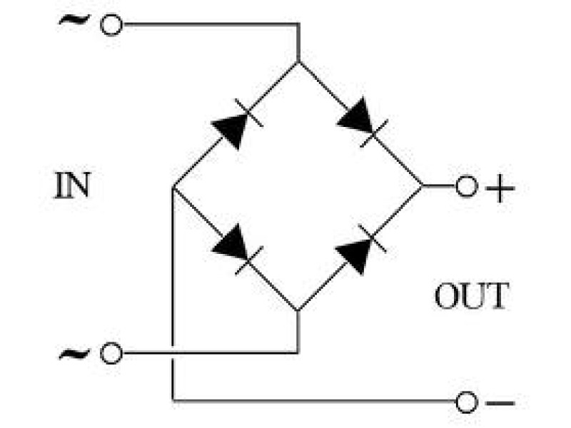
A diode bridge (bridge rectifier) is a configuration of four diodes arranged to convert AC to DC. Testing a diode bridge ensures it is functioning correctly by verifying each diode’s conduction in the forward direction and blocking in reverse.
⚠ Important: To get accurate results, desolder or remove the bridge from the circuit, as other components can skew the readings.
1. Understanding the Diode Bridge
A four-diode bridge has:
- Two AC input terminals (for the AC supply)
- + output terminal
- - output terminal
Each internal diode must be tested for forward conduction and reverse blocking.
Common Pinout (Reference)
Shop this topic
Browse Multimeters Related products from Safsale
Continue from Academy guidance to live equipment and components available on Safsale.


