Electrical Wiring Inspection in Your Home – Tools, Diagnosis, and Safety Tips
Your home’s electrical wiring is a critical component that powers every aspect of modern living. While it ensures comfort and convenience, faulty wiring can lead to serious hazards, including short circuits and fires. A regular inspection helps identify hidden issues and prevent catastrophic failures.
Statistics reveal that over 30% of residential fires are caused by electrical faults, emphasizing the importance of regular diagnostics and preventive maintenance. For homes over 20 years old, an annual inspection is highly recommended, as older wiring systems were not designed to handle today’s high-power appliances.
Step 1: Visual Inspection – The First Line of Defense
A visual inspection is a crucial first step in assessing the state of your electrical wiring. Focus on identifying obvious signs of wear and damage.
What to Check:
- Outlets and Switches: Look for discoloration, melting, or burn marks on outlet covers. These could indicate overheating or poor connections.
- Wiring Connections: In junction boxes, ensure wires are properly secured with connectors or wire nuts. Exposed wires and poor connections may lead to sparking or short circuits.
- Insulation Condition: For visible wiring, inspect the insulation for cracks, abrasion, or visible damage. If your wiring is hidden behind walls, be alert for hot spots or discoloration on the wall surface.
Hidden Issues to Watch For:
In older homes, problems may not be immediately visible. If you suspect hidden damage, look for subtle signs like flickering lights, unexplained power outages, or a burning smell. These are clear indicators that a deeper inspection is necessary.
Step 2: Instrumental Diagnostics for Electrical Wiring
Visual inspection is just the beginning. Comprehensive diagnostics require specialized tools to measure voltage, resistance, and continuity. Here’s how to get it done.
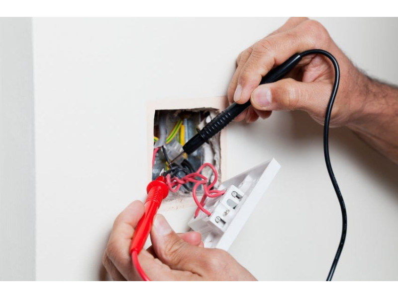
Voltage Testing
Using a multimeter, measure the voltage at each outlet. In U.S. homes, the standard voltage should be approximately 120V (±10%) for single-phase outlets.
Significant voltage fluctuations could indicate wiring issues or problems with your power supply.
Insulation Resistance Testing
Insulation resistance is a key indicator of the health of your wiring. Low insulation resistance can lead to leakage currents and potential fires. Use a megohmmeter to perform this test:
- Turn off all connected appliances and disconnect power at the main breaker.
- Test between live (phase) and neutral, as well as between live and ground.
The insulation resistance should be no less than 0.5 MΩ. Any value below this threshold indicates degraded insulation that needs immediate attention.
Step 3: Grounding and Protective Systems Check
A properly grounded electrical system is essential for safety. Inspect and test the grounding system to ensure its reliability.
Grounding Resistance Measurement
Using a ground tester, check the resistance of your grounding system. For residential properties, the recommended maximum is 4 ohms. A higher reading suggests a poor connection that needs correction.
In modern electrical systems, ensure all outlets have a working ground wire. Improper grounding can expose users to electrical shock hazards.
Step 4: Testing Circuit Protection Devices
Residual Current Devices (RCDs) or Ground Fault Circuit Interrupters (GFCIs)
RCDs or GFCIs are critical for protecting against electric shock. Regularly test their functionality:
- Press the test button—the device should immediately cut power.
- If it doesn’t respond, replace the device.
For advanced testing, use a specialized tester to measure response time and ensure it disconnects within 0.03 seconds at 30 mA leakage.
Circuit Breaker Check
Circuit breakers protect wiring from overload and short circuits. Check for proper operation and ensure they match the current rating of the protected circuit. A misaligned or sluggish breaker mechanism indicates the need for replacement.
Step 5: Load Balancing in Three-Phase Systems
In three-phase systems, uneven load distribution can cause serious problems. Use current clamps to measure current in each phase. A difference exceeding 15% between phases indicates an imbalance that must be corrected by redistributing loads.
Step 6: Advanced Thermal Imaging Diagnostics
A thermal imaging camera is an invaluable tool for detecting hidden issues.
What Thermal Imaging Can Reveal:
- Overheated connections
- Poor contact points in distribution panels
- High-resistance faults in cables or junction boxes
Conduct the scan during peak load times for the most accurate results.
Preventive Measures and Maintenance Recommendations
Prevention is always better than a cure. Implement these measures to keep your electrical system in top shape:
- Tighten Connections: Periodically inspect and tighten connections in your breaker box.
- Replace Worn Components: Don’t wait for failures—replace old outlets, switches, and breakers as part of regular maintenance.
- Modernize Outdated Wiring: In older homes, consider upgrading from aluminum wiring to copper for improved safety and performance.
- Document Inspections: Keep a record of all inspections and maintenance. This allows you to track trends and plan for future upgrades.
When to Call a Professional
Some tasks require specialized knowledge and tools. For complex diagnostics like insulation resistance testing, grounding repairs, or thermal imaging, it’s best to call a licensed electrician. Safety should always be your top priority.
Conclusion
Regular electrical wiring inspections are not just a smart safety practice—they’re essential for preventing costly repairs and ensuring the long-term reliability of your electrical system. Comprehensive diagnostics, combined with preventive maintenance, can significantly reduce the risk of hazards like short circuits, fire, and electrocution.
For more expert advice, diagnostic tools, and professional-grade electrical equipment, visit safsale.com. Protect your home and ensure your family’s safety with our detailed guides and high-quality products.