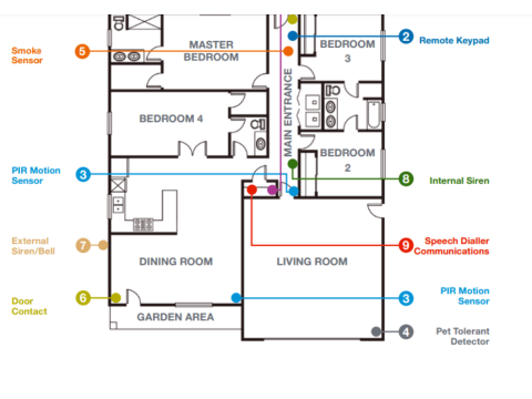
Comprehensive Guide to Security Alarm System Schematics and Sensor Connections
Building an efficient and reliable security alarm system requires understanding its structure and sensor connection principles. This guide outlines the essential components, schematics, and connection methods for security alarms.
Key Components of a Security Alarm System
A typical security alarm system includes the following elements:
- Control Panels (PCP): Manage and monitor the system.
- Sensors (IO): Detect intrusion, motion, or other anomalies.
- Power Supplies (BP): Ensure uninterrupted operation.
- Alert Devices: Includes visual (OS) and audible (OZ) alarms for notifications.
- Transmission Units (SPI): Used for remote monitoring in centralized systems.
System Structure and Configuration
A typical security alarm system’s block diagram (Fig. 1) highlights the interconnection of all essential components. Some systems integrate multiple functions into a single unit, such as GSM-enabled control panels that combine monitoring and transmission features.
Power Supply Considerations
- Direct Powering: Sensors and PCPs may rely on dedicated power lines.
- Integrated Power: Some sensors receive power through alarm loops.
Sensor Connection Principles
The connection of security sensors depends on their design and operation. Below are common sensor types and their corresponding wiring methods.
Types of Sensor Connections
1. Sensors with Relay Outputs
These are the simplest type, requiring minimal wiring.
- Normal Connection (Normally Closed): Sensors are connected in series to break the loop upon activation (Fig. 2a).
- Alternate Connection (Normally Open): Sensors are connected in parallel but are less common in practice (Fig. 2b).
Wiring Diagram for a Sensor with Relay Output
- Power is supplied via a separate circuit, making the setup four-wire.
- Magnetic-contact sensors, which detect door/window openings, do not require separate power (Fig. 3).
2. Sensors Powered via Alarm Loops
Used in addressable and non-addressable systems, these sensors receive power directly from the loop.
Addressable Sensors
- Transmit data digitally, allowing precise identification.
- Require strict adherence to polarity.
- Wiring Configuration: Two-wire loops, with sensors connected in parallel (Fig. 4).
Non-Addressable Sensors
- Operate by increasing current flow during activation.
- Share the same wiring configuration as addressable sensors but lack unique identification.
Key Considerations for Sensor Connections
- Polarity: Ensure the correct orientation of positive and negative connections.
- Current Limits: The number of sensors per loop is dictated by:
- Loop Current Capacity: Defined by the control panel.
- Sensor Current Draw: Specified in device manuals.
Manufacturers often provide wiring guides in installation manuals to simplify the process.
Best Practices for Wiring and Installation
- Secure Mounting: Place control panels within secured areas to prevent tampering.
- Zoning: Divide sensors into zones for better monitoring and fault detection.
- Documentation: Follow manufacturer-provided schematics for accurate wiring.
- Testing: Conduct thorough post-installation testing to ensure system reliability.
Conclusion
A well-designed security alarm system begins with understanding its schematics and sensor connections. Proper planning, adherence to wiring standards, and attention to detail ensure optimal performance. For more guidance on designing and installing security alarm systems, visit safsale.com

