How to Test and Diagnose Home Electrical Wiring with a Multimeter
Your home’s electrical wiring is a vital system that ensures the seamless operation of all electrical appliances and lighting. Regular checks of your wiring can help prevent potential issues like short circuits, electrical fires, and equipment failure. Using a multimeter is one of the most effective ways to check the condition of your wiring and detect problems early.
According to safety statistics, a significant portion of residential fires in the USA is caused by electrical faults. Understanding how to test and maintain your wiring is essential for your family’s safety.
What You’ll Need for Testing Electrical Wiring
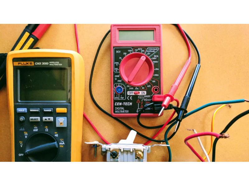
The key tool for testing electrical wiring is a multimeter. This versatile device can measure voltage, resistance, and continuity, making it invaluable for diagnosing issues in your home’s electrical system.
Other Essential Tools
- Non-contact voltage tester – for detecting live wires.
- Insulated screwdriver and pliers – for safely accessing wiring.
- Insulating tape – for temporary repairs.
When selecting a multimeter, ensure it has the following features:
- AC/DC Voltage Measurement
- Resistance Measurement (Ohmmeter Function)
- Continuity Test with Sound Indicator
Step 1: Preparing for Wiring Inspection
Before testing your electrical system, follow these steps for safety:
- Turn off power at the main circuit breaker or fuse box for the circuit you’re testing.
- Check for live wires using a non-contact voltage tester to confirm the power is off.
- Review your home’s wiring layout or try to visualize the general path of the wires. This will help you locate potential problem areas faster.
Step 2: Testing Electrical Continuity
What is Continuity Testing?
Continuity testing checks whether an electrical path is complete. It helps detect broken wires, faulty switches, or disconnected circuits.
Steps to Test Continuity with a Multimeter:
- Set the multimeter to the continuity mode (often symbolized by a sound wave or buzzer icon).
- Touch the multimeter probes to the two ends of the wire or circuit you want to test.
- If the circuit is intact, the multimeter will emit a beeping sound, indicating continuity. If there’s no sound, the wire or circuit is broken.
Step 3: Checking Insulation Resistance
Insulation resistance testing helps detect worn or damaged insulation that could lead to current leakage or short circuits. While a full test requires a megohmmeter, a multimeter can provide a basic assessment.
How to Test Insulation:
- Set the multimeter to the resistance mode (Ω) with the highest range.
- Place one probe on the live wire and the other on ground (earth).
- A high resistance value indicates good insulation, while a low reading suggests damage or moisture.
Note: For precise results, use a dedicated insulation tester (megohmmeter).
Step 4: Voltage Testing
Voltage testing ensures that your outlets and circuits are receiving the correct amount of electricity.
How to Measure Voltage:
- Set the multimeter to AC voltage mode (V~).
- Insert the probes into the outlet slots (one in the live slot, the other in the neutral).
- The reading should be around 120V in most U.S. residential circuits.
If the reading is too low or too high, it may indicate a wiring problem or power supply issue.
Common Issues and How to Detect Them
1. Short Circuits
- Symptoms: Tripped breakers, sparks, or sudden power loss.
- Diagnosis: Measure resistance between live and neutral wires. A very low resistance indicates a short circuit.
2. Ground Faults and Current Leakage
- Symptoms: Frequent trips of Ground Fault Circuit Interrupters (GFCIs).
- Diagnosis: Measure resistance between live and ground wires. Low resistance means current is leaking.
3. Poor Connections or Corroded Contacts
- Symptoms: Flickering lights, intermittent power, or warm outlets.
- Diagnosis: Measure continuity at connection points. Replace corroded or loose connections.
Hidden Wiring Problems – Testing Schematic and Strategy
For hidden wiring, start by testing the most accessible points—outlets, switches, and junction boxes. Work methodically from the circuit breaker panel outward.
Advanced Diagnostics
- Thermal imaging cameras can reveal overheated wires or poor connections.
- Current clamps can monitor real-time current flow in each circuit without disconnecting wires.
Safety Tips for Electrical Testing
- Always turn off the power before opening junction boxes or outlets.
- Use insulated tools to prevent accidental shocks.
- Do not work alone—have someone nearby in case of emergencies.
- Wear protective gear, including rubber gloves and safety glasses.
- If you detect a serious issue, call a licensed electrician.
When to Seek Professional Help
Certain situations, such as recurring tripped breakers, persistent low voltage, or signs of overheating, require professional intervention. Licensed electricians have specialized tools like megohmmeters and thermal cameras to provide a more accurate diagnosis.
Conclusion
Regular electrical wiring testing is an essential part of home maintenance. With the right tools and knowledge, you can identify and address issues before they become serious hazards.
For more information on electrical diagnostics, tools, and safety equipment, visit safsale.com—your trusted source for professional-grade solutions.