Connecting an RCBO (Difavtomat) in a Single-Phase Network
In many USA households, you might already be familiar with GFCI (Ground Fault Circuit Interrupter) breakers that protect against electrical shock, as well as standard circuit breakers for overcurrent protection. An RCBO (Residual Current Circuit Breaker with Overcurrent, also known as a difavtomat in some markets) essentially combines these two functions into one device, saving space in your panel and simplifying your wiring.
This guide covers how to connect an RCBO (difavtomat) in a single-phase system, both with and without grounding. While the principles remain similar to installing a separate GFCI and standard breaker, there are several crucial details to watch for-especially if you want to meet USA codes and ensure maximum electrical safety.
Tip: For additional insights on electrical products, wiring best practices, and USA code compliance, check out safsale.com. You’ll find resources on single-phase connections, recommended RCBO brands, and more.
1. RCBO (Difavtomat) Basics: Why It’s Beneficial
Since an RCBO combines circuit breaker (overcurrent protection) and RCD (residual current or ground-fault detection) in one unit, installing a single device can:
- Reduce overall cost of hardware.
- Simplify wiring by handling both hot and neutral connections in a consolidated unit.
- Save space in a crowded breaker panel.
- Protect against both overcurrent (short circuit, overload) and ground faults (leakage current).
Though the term difavtomat might be less common in the USA, the concept remains the same. It’s essentially an all-in-one breaker that trips in the event of either a fault to ground or an overcurrent situation.
2. General Wiring Principles
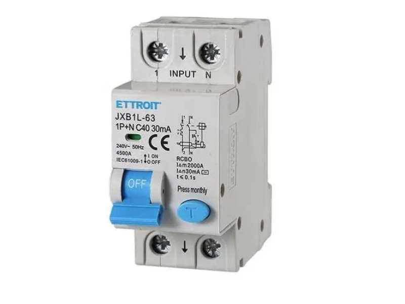
Even though it’s a combined device, an RCBO typically features a hot (L) input and a neutral (N) input at the top (line side), with corresponding outputs for hot and neutral at the bottom (load side). Look carefully at the device markings:
- L (Line/Hot)
- N (Neutral)
- PE (Protective Earth or Ground) - If your system includes a separate ground conductor.
- PEN - In some systems outside the USA, there may be a combined ground and neutral, but most modern American installations use a dedicated neutral and equipment ground.
Important: Always connect the feed (input from the meter or panel bus) to the top of the device as indicated, and the outgoing load (wiring to fixtures/outlets) to the bottom. Never reverse these connections.
Potential Wiring Mistakes to Avoid
- Crossing Hot and Neutral
Don’t wire them “criss-cross” (hot in on one side, hot out on the opposite). - Mixed Inputs and Outputs
Ensure the line (power supply) and load (protected circuit) aren’t swapped between top and bottom. - Combining Neutrals
If you have multiple RCBOs in your panel, each must have its own neutral connection. Never share a neutral bus for different RCBO-protected circuits on the load side.
3. Connecting an RCBO in a Single-Phase Network Without Grounding
Some older USA homes lack a dedicated equipment grounding conductor. In that case:
- Hot (L) and Neutral (N) Feeds
- Attach the hot feed to the labeled L in terminal on the RCBO.
- Attach the neutral feed to the N in terminal on the RCBO.
- Outputs to Load
- The hot output (L out) goes to the circuit you’re protecting.
- The neutral output (N out) goes to the same circuit’s neutral conductor.
- No Ground
- Since there’s no dedicated PE conductor, the chassis of devices (like washing machines, kitchen appliances) is often left ungrounded unless local code allows a retrofitted ground or neutral.
- Any ground fault or current leakage to a device’s metal enclosure still triggers the RCBO via the detected imbalance between hot and neutral.
Note on Neutral: Each RCBO-protected circuit should have its own neutral wire returning to the RCBO neutral output. Do not tie neutrals together downstream, or you can compromise fault detection.
How It Works Without Ground
If a live conductor accidentally touches the metal casing of an appliance and you touch that casing, leakage current flows through you to earth. The RCBO senses the imbalance between hot and neutral, immediately trips, and prevents electrocution-even without a formal ground wire.
4. Connecting an RCBO in a Single-Phase Network With Grounding
In a modern USA installation, your service panel typically provides:
- Hot (L)
- Neutral (N)
- Ground (PE)
The RCBO installation is fundamentally the same as above, but now you have an additional PE (ground) conductor:
- Hot (L) in goes to RCBO line terminal.
- Neutral (N) in goes to RCBO neutral terminal.
- Hot (L) out feeds your circuit’s live conductor.
- Neutral (N) out feeds your circuit’s neutral conductor.
- PE (ground) bypasses the RCBO entirely and connects directly to the device’s chassis or to the grounding bus as per USA code.
Why the Ground Bypasses the RCBO
When a ground fault occurs, current will prefer the low-resistance path to ground (the PE conductor) outside the RCBO. Because the RCBO measures any difference between hot and neutral, that off-balance flow instantly triggers the internal detection mechanism, opening the circuit and cutting power.
Example: If you have a grounded metal washing machine housing, and a hot wire contacts the housing, the fault current flows via the PE wire straight back to the panel’s ground bus. The RCBO sees the mismatch (hot current doesn’t fully return via its neutral terminal) and trips immediately, protecting the user.
5. Common Pitfalls and Best Practices
- Mislabeling or Mixing Line/Load
- Always follow the arrows or “In/Out” markings on the RCBO.
- Incorrect Neutral Wiring
- Never share neutrals across multiple RCBO-protected circuits. Each circuit’s neutral must stay separate all the way back to the specific RCBO that protects it.
- Improvised Grounding
- You can’t simply tie your appliance chassis to a neutral conductor on the load side of the RCBO and call it a day. This can create dangerous potential on neutral wires.
- If local code allows a bonding jumper at the service panel, ensure it’s done per NEC (National Electrical Code) guidelines.
- Overcrowded Panel
- When installing multiple RCBOs, check that your panel has enough space. Overheating or awkward wiring can compromise both function and safety.
6. Ensuring Code Compliance in the USA
- National Electrical Code (NEC) updates frequently. The latest version mandates GFCI or RCBO protection in areas like kitchens, bathrooms, garages, crawl spaces, unfinished basements, and outdoor receptacles.
- Proper grounding is crucial. If your home is older, consider hiring a licensed electrician to add an equipment grounding conductor or upgrade your panel.
- Markings and Labels: Ensure all breakers, circuits, and sub-panels are properly labeled, making future troubleshooting or renovations easier.
Pro Tip: Visit safsale.com for updated code references, recommended products, and wiring examples that meet modern USA standards.
7. Conclusion
An RCBO (difavtomat) is a versatile electrical safety device that can significantly simplify your single-phase wiring by combining overcurrent and ground-fault protection. Whether your system has a dedicated ground conductor or not, you can install an RCBO to safeguard against shocks, short circuits, and overloads in one streamlined package.
Key Points to Remember
- Always maintain proper line (input) and load (output) orientation.
- Avoid mixing neutrals from multiple RCBO-protected circuits.
- If you have a ground (PE) conductor, connect it outside the RCBO so that any leakage current bypasses the device, triggering a trip.
- If no dedicated ground exists, the RCBO still offers protection by detecting current imbalances between hot and neutral.
- Consult the NEC and local codes, especially if you’re upgrading an older home.
By following these guidelines and ensuring compliance with USA electrical codes, you can enjoy the enhanced protection of an RCBO and reduce both cost and complexity in your next electrical project. For more tips, device comparisons, and code-compliant solutions, be sure to explore safsale.com and stay updated on the latest in electrical safety innovations.
Stay safe, wire smart, and protect your home with the best practices in single-phase RCBO (difavtomat) installation-your safety and peace of mind are worth the extra diligence.