How a Solid-State Relay Works
A solid-state relay functions like other relays in that it switches a high-power circuit using a low-power control signal. However, unlike traditional electromechanical relays, solid-state relays (SSRs) use semiconductor components (e.g., triacs, thyristors, transistors) instead of mechanical contacts.
Basic Principle
In most SSR designs, you’ll find:
- High-Power Semiconductor Switch (often a triac for AC loads)
- Low-Power Control Circuit with galvanic isolation (e.g., an optocoupler)
- Input Resistor or other limiting components
When a small control current flows on the input side, the internal optocoupler activates, triggering the semiconductor switch so it conducts current to the load.
Key Benefit: Because there are no mechanical contacts, solid-state relays switch quickly, operate silently, and are less prone to arcing or contact wear.
Illustrative Example
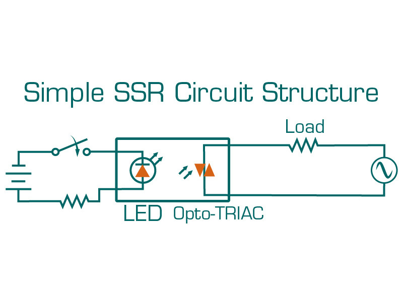
Consider a simplified diagram with:
- R (current-limiting resistor)
- VS (triac or thyristor)
- VU (optocoupler)
- U_ctrl (control voltage)
- U_load (load voltage)
Steps in operation:
- Control voltage applied - A small current flows through the input LED inside the optocoupler.
- LED activates phototransistor - The phototransistor output signal triggers the triac or thyristor gate.
- Triac conducts - The main load circuit is powered by U_load.
Most solid-state relays come in a modular housing and can be panel-mounted or installed in DIN rail enclosures.
Advantages & Disadvantages
Pros:
- Fast switching (practically instantaneous)
- Long service life (no mechanical parts to wear out)
- No contact arcing (reduces electromagnetic interference)
- Silent operation
Cons:
- Sensitive to overloads and short circuits - SSRs can fail if currents exceed design limits.
- Relatively high cost - Often more expensive than electromechanical equivalents.
- Requires careful sizing and upstream short-circuit protection (e.g., correctly rated breakers).
Recommendation: Use solid-state relays in high-frequency switching applications or where silence is crucial-provided the load and breaker coordination are well-chosen.
Key User Specifications
- Control Method - DC or AC control input, with specific voltage or current range.
- Load Ratings - Maximum voltage, current, and power the SSR can switch.
Single-phase and three-phase SSR models are available depending on system requirements.
Control and Connection Examples
Solid-state relays typically have four terminals:
- Terminals 1 & 2 - Load (output, or switched side)
- Terminals 3 & 4 - Control (input, or coil side in older relay terminology)
Example 1: Voltage Drive (3-32 V DC)
Many SSRs use a low-voltage DC input (e.g., 3-32 V). This voltage can come from:
- A dedicated power supply or converter
- Dry contacts on a small control relay or switch
- An electronic control circuit (PLC, microcontroller, etc.)
When the SSR sees the appropriate DC voltage across its input terminals, it closes the internal semiconductor switch, powering the load. Removing the voltage opens the circuit.
Note: If you use a device with normally closed contacts to drive the SSR, you invert the on/off logic (i.e., the SSR is energized when the contacts are closed).
Example 2: Current Drive
Some SSRs are triggered by a specific input current. An external resistor R is often used to limit current:
- I_ctrl - Desired control current
- U_ctrl - External supply voltage
- U_p - Voltage drop on the SSR input (e.g., LED drop of about 2 V)
Such designs are less common but still found in specialized applications.
Example 3: AC Line Control
Certain SSRs can accept AC line voltage as the control signal. Advantages include:
- No separate control supply required
- Straightforward wiring for start/stop push-buttons and contact-based controls
Final Thoughts
A solid-state relay is ideal for applications needing quiet, high-speed, and high-cycle switching. They’re widely used in heating controls, motor drives, and lighting where frequent on/off cycles could wear out mechanical relays. Always ensure:
- Appropriate Load Protection - An SSRs can be damaged by overcurrent or short-circuit conditions.
- Proper Heat Dissipation - Larger SSRs often require a heatsink.
- Accurate Sizing - Match the voltage and current ratings to your load and environment.
By selecting the right SSR design (single-phase or three-phase, DC or AC control) and providing overcurrent protection, you can benefit from reliable, long-lasting, and low-interference switching in demanding applications.