FIRE ALARM WIRING: HOW IT ALL CONNECTS
SENSORS
CONTROL PANELS
ALERT SYSTEMS
Setting up a fire alarm system isn’t just about plugging wires into boxes-it’s about creating a seamless connection between sensors, control panels, and notification systems. Let’s break it down step-by-step, starting with the basics.
THE FIRE ALARM STRUCTURE
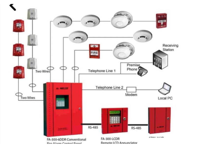
Here’s what a typical wired fire alarm system looks like:
- Control Panel (CP): The brains of the operation.
- Sensors (Detectors): Smoke, heat, or flame detectors that identify fire hazards.
- Notification Devices: Buzzers, alarms, or strobes that alert people.
- Auxiliary Equipment: Controls for fire suppression or smoke extraction systems.
- Power Supply: Either internal or external, depending on the system.
Some control panels, like VERS or Granite, come with built-in power sources, making external power blocks unnecessary-unless specific sensors (like beam detectors) need separate voltage inputs.
HOW TO WIRE FIRE ALARM SENSORS
In most wired fire alarm systems, sensors are connected using loops. The most common setup is a two-wire loop, which combines power and data transmission over the same line.
Basic Two-Wire Setup:
Components:
- Sensor (IP): The main detection device.
- End-of-Line Resistor (Rok): Maintains the loop’s current in normal operation.
- Additional Resistor (Rdop): Limits current when a sensor is triggered.
How It Works:
- The control panel monitors current changes to detect states like "Attention" (one sensor activated) or "Fire" (multiple sensors triggered).
- The resistor values depend on the specific sensor and control panel, as outlined in their technical docs.
Common Sensor Types:
- Smoke Detectors: Test with aerosols or visual inspections.
- Heat Detectors: Carefully apply heat using tools like hairdryers. Avoid flames to prevent damage.
- Flame Detectors: Use a flame source within the sensor’s detection range for testing.
Always double-check the manufacturer’s wiring diagram for resistor placement and polarity.
CONTROL PANEL CONNECTIONS
Every control panel (CP) comes with its unique terminal setup, but the principles are generally the same:
Loops and Zones:
- Each loop monitors a specific area or group of sensors.
- Some systems share a common wire for multiple loops to save on wiring.
External Devices:
- Outputs control connected devices like alarms, lights, or smoke extractors.
- Power is delivered through relay contacts or open collector outputs.
Power Supply Options:
- Direct from the Grid (220V): Requires an internal backup battery to ensure uninterrupted operation.
- External Power Block: The control panel connects to an external source via dedicated terminals.
FIRE ALARM WIRING DIAGRAMS
Basic Smoke Detector Connection:
- Four terminals on the detector’s base:
- Terminals 1 and 2: Connect to the loop.
- Terminals 3 and 4: Usually shorted in normal operation.
- If the detector is removed or malfunctions, this connection breaks, signaling a "Fault."
Advanced Configurations:
- Some setups include diodes or external indicators for enhanced monitoring.
- Addressable sensors connect in parallel without resistors, simplifying installation.
BEST PRACTICES FOR WIRING FIRE ALARM SYSTEMS
- Follow Manufacturer Guidelines: Every component has unique requirements.
- Test Connections: Simulate faults and alarms to ensure everything works as expected.
- Double-Check Polarity: Especially important for addressable sensors and powered loops.
- Document the Setup: Keep a record of all connections and configurations for future maintenance.
With these principles, you’re ready to wire a fire alarm system that’s both functional and reliable. If you need further guidance, feel free to ask!