A Hall effect sensor is a magnetic transducer that converts a magnetic field strength into an electrical signal. By detecting changes in a magnetic field, these sensors are widely used in automotive applications (e.g., for ignition timing and speed sensing), as well as in consumer electronics (laptops, phones) to sense closures or measure current without direct electrical contact.
Below, we explore how Hall effect sensors work, their major types, typical uses, and quick tests to diagnose potential failures.
1. How a Hall Effect Sensor Works
1.1 Hall Effect Principle
The Hall effect arises when charged particles (electrons) in a conductor experience the Lorentz force in the presence of a magnetic field:
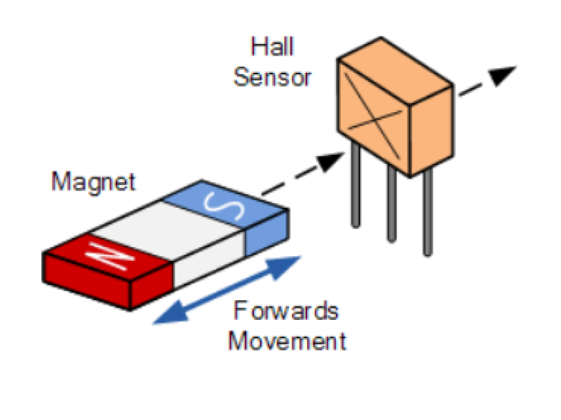
- Current Flow: A regulated current passes through a thin, flat conductive or semiconductor element.
- Magnetic Field: Positioned so that magnetic lines intersect the element’s plane at a right angle.
- Voltage Generation: The magnetic force shifts electrons sideways, creating a small voltage difference across the element’s other edges. This tiny voltage (often up to ~100 mV) is proportional to the magnetic field strength and direction.
1.2 Key Components
Modern Hall sensors incorporate:
- Hall Element (Semiconductor): Generates the base Hall voltage.
- Signal Conditioning: An amplifier or comparator to produce a practical output signal.
- Magnetic Circuit: Often includes a small permanent magnet or ring to stabilize the field or interact with ferromagnetic rotors.
2. Types of Hall Effect Sensors
2.1 Analog vs. Digital
-
Analog Hall Sensors:
- Provide a voltage output proportional to the magnetic field magnitude (and direction if designed for bipolar output).
- Commonly used for measuring current or position where a continuous reading is needed.
-
Digital (Switching) Hall Sensors:
- Output is typically "on" or "off" based on whether the magnetic field crosses a threshold.
- Variations:
- Unipolar - Switch triggers with one polarity of magnet.
- Bipolar - Switch toggles on one magnetic pole, off with the opposite pole.
2.2 Automotive Applications
In automotive ignition or cam/crank sensing:
- A ferromagnetic rotor or gear passes by the sensor’s magnet or field area.
- As teeth pass: The sensor’s output toggles near the rotor’s notches, indicating precise rotational position.
- Why Hall? No mechanical contacts, minimal wear, stable switching points, accurate timing for spark generation.
3. Common Uses of Hall Sensors
- Automotive Engine Management: Determining crankshaft/camshaft position for ignition and fuel injection timing.
- Current Sensing: Measuring DC or AC currents in power electronics by monitoring the magnetic field produced by a conductor.
- Consumer Electronics: Laptop lid or phone fold sensors that “tell” the system to sleep or wake.
- Speed and Position Detection: In BLDC motors (brushless DC), for commutation feedback.
- Door/Window Alarms: Digital Hall sensors detect the presence or absence of a magnet.
4. How to Test a Hall Effect Sensor
4.1 Common Failure Symptoms
- Engine Struggles to Start: Or random stalling, indicating inconsistent timing signals.
- Erratic Speed or RPM Readings: Hall sensor output might be unstable.
- Random Misfires: Caused by missing or spurious pulses from the sensor.
4.2 Quick Testing Methods
- Sensor Swap: In automotive contexts, substituting with a known-good sensor is often the easiest approach.
- Multimeter Check (Voltage):
- Power the sensor as usual (connect negative to chassis ground, positive to battery voltage).
- Measure the output (signal) line with respect to ground while placing a ferromagnetic blade (like a steel strip) to interrupt or block the sensor’s field.
- Expect a near supply voltage (~11-12 V in a 12 V system) if the magnetic field is unobstructed, and near 0 V when metal blocks or modifies the field.
- Advanced Tools: Using an oscilloscope to visualize the sensor’s switching waveforms. Typically for specialists.
5. Advantages and Limitations
5.1 Pros
- Contactless Operation: No mechanical wear or “switch bounce.”
- Stable Switching Points: Precisely repeated transitions.
- Versatile: Suited for measuring current, position, or motion in diverse setups.
- Low Cost & Compact Size: Integration into microchips allows wide adoption.
5.2 Cons
- EMI Sensitivity: Must often be shielded in strong electromagnetic environments (like ignition circuits).
- Reliance on Magnetic Fields: Requiring stable magnets or ferromagnetic structures.
- Electronic Complexity: Some sensor circuits add cost or complexity compared to purely mechanical solutions.
Conclusion
A Hall effect sensor harnesses magnetic field interactions to produce precise on/off or analog signals. In automotive engines, it eliminates mechanical contact points, enhancing reliability and timing accuracy. Elsewhere, it underpins current sensing, speed detection, or simply toggling device states in consumer gadgets.
Symptoms like engine misfires or stalling can indicate Hall sensor issues. Quick tests involve substituting a known-good unit or measuring output voltage while manipulating the sensor’s magnetic path. Although they can be sensitive to EMI and rely on stable magnetic fields, Hall effect sensors remain indispensable in modern electronics for their stable switching, contactless operation, and cost efficiency.
For more guidance on selecting the right Hall sensor or diagnosing issues, safsale.com offers in-depth resources and support for automotive and industrial applications.