Installing a Video Intercom System has evolved from being a luxury amenity for affluent individuals to a necessary security measure for every household and apartment. The monitor is a crucial element of this security system, serving as the central hub for communication, monitoring, and access control. While installation may seem straightforward with a clear connection scheme, the reality often involves navigating through incomplete manuals and varying compatibility between components. This guide aims to provide practical recommendations and detailed insights to help homeowners and tenants confidently install and connect their video intercom systems, ensuring a secure and functional setup.
Video Intercom Installation: Key Components
When undertaking the installation of a video intercom system, it's essential to understand the primary components involved:
- External Call Panel: Installed at the entrance, equipped with a camera, speaker, microphone, and call button.
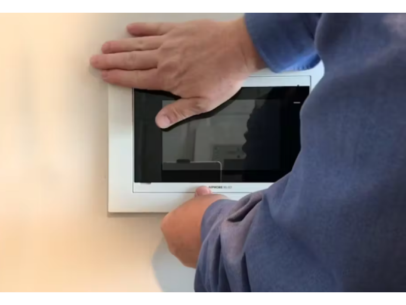
- Monitor (Central Control Panel): Located inside the building, displays video feeds, facilitates communication, and controls the locking mechanism.
- Electric Lock: Can be electromagnetic or electromechanical, responsible for securing doors, gates, or entry points.
- Additional Cameras (Optional): For extended surveillance coverage.
- Installation Accessories: Includes connectors, cables, mounting hardware, and potentially controllers or adapters.
Practical Installation Tips
1. Essential Preparation
Before starting the installation, ensure you have all necessary components and tools:
- Complete Kit: Verify that your video intercom kit includes the monitor, external call panel, electric lock, and all necessary wiring and connectors.
- Compatibility Check: Ensure that the monitor and external call panel are compatible, preferably from the same manufacturer to guarantee seamless integration.
- Tools Required: Screwdrivers, drills, cable testers, wire strippers, and possibly a multimeter for electrical checks.
2. Follow Manufacturer Instructions
While many manufacturers provide manuals, they are often incomplete or overly technical. It's crucial to:
- Read Available Documentation: Study any available diagrams or instructions thoroughly.
- Seek Additional Resources: Look for online tutorials, forums, or contact customer support for clarification on complex steps.
- Plan the Layout: Determine the placement of each component before mounting to minimize errors and rework.
Connection Schemes
a. Understanding the Connection Diagram
A typical video intercom connection scheme involves:
- Four-Wire Cable: Used to connect the external call panel to the monitor, carrying video, audio, power, and ground signals.
- Coaxial Cable (Optional): May be used for extended video signal transmission to prevent interference.
- Separate Power Lines for Locks: Especially important for electromechanical locks that require significant current.
b. Dealing with Signal Interference
When using a four-wire cable for video transmission:
- Potential Issues: Long cable runs can introduce signal interference, resulting in distorted images.
- Solution: Utilize coaxial cables with a 75-ohm impedance (e.g., RG-6, RG-59) for better signal integrity over longer distances.
- Testing: Assemble the system on a table before permanent installation to identify and rectify any interference issues by swapping or rerouting cables.
c. Connecting to the Monitor and Call Panel
- Video Signal: Connect the video output from the call panel to the video input on the monitor.
- Audio Signal: Ensure that the speaker and microphone lines are correctly connected for two-way communication.
- Power Supply: Verify that the monitor is properly connected to the power source, and that the call panel receives power either from the monitor or a separate adapter.
- Grounding: Properly ground all components to prevent electrical issues and ensure system stability.
Connecting Locks to the Video Intercom
a. Types of Electric Locks
Electromagnetic Locks:
- Operation: Remain locked when power is supplied; unlock when power is removed.
- Usage: Commonly used in high-traffic areas like apartment entrances.
- Considerations: Requires a separate controller for proper signal inversion.
Electromechanical Locks:
- Operation: Remain locked without power; unlock with a brief electrical pulse.
- Usage: Widely used in private homes for gates and entrance doors.
- Advantages: Offer a mechanical override (e.g., key) for emergency access.
b. Connection Methods
1. Connection to a Separate Controller
- Purpose: Facilitates the integration of electromagnetic locks with call panels that have normally open contacts.
- Steps:
- Acquire a Compatible Controller: Ensure it matches the lock type (electromagnetic or electromechanical).
- Wiring: Connect the lock to the controller using the provided wiring diagram.
- Integration: Link the controller to the call panel, allowing the intercom system to manage lock operations.
2. Direct Connection to the Call Panel
- Purpose: Simplifies the setup by connecting locks directly to the intercom system without additional controllers.
- Steps:
- Assess Power Requirements: Ensure the call panel can handle the current draw of the lock.
- Wiring: Connect the lock to the call panel using high-gauge wiring (e.g., 1.5mm²) to support the necessary amperage.
- Testing: Verify that the lock operates correctly via the intercom system.
c. When a Controller is Necessary
- Electromagnetic Locks: Often require controllers to invert signals, allowing the intercom system to unlock the door when appropriate.
- Multiple Lock Management: Controllers enable the management of several locks from a single intercom system, essential for multi-unit buildings.
Installation for Homes and Apartments
a. Installation in Private Homes
Typical Setup:
- Primary Locations: Entrance door and potentially gate or backyard doors.
- Lock Integration: Electromechanical locks are preferred for their reliability and manual override capabilities.
- Additional Cameras: Optional cameras can be installed for broader surveillance coverage.
Steps:
- Mount the External Call Panel: At an optimal height (140-150 cm) near the entrance.
- Install the Monitor: In a central indoor location for easy access and visibility.
- Connect the Lock: Choose between electromagnetic or electromechanical based on security needs.
- Test the System: Ensure all components communicate correctly and the lock operates as intended.
b. Installation in Apartments
Typical Setup:
- Primary Locations: Shared entrance or multiple individual apartment doors.
- Lock Integration: Often use electromagnetic locks in shared entrances; individual apartments may have their own electromechanical locks.
- Centralized Management: Switchboards or controllers may be used to manage multiple intercom panels and locks.
Steps:
- Coordinate with Neighbors: Ensure compatibility and agree on common system features.
- Mount External Call Panels: At each entry point, ensuring secure and accessible placement.
- Install Monitors: Inside each apartment, ensuring they are connected to the respective external panels.
- Connect Locks: Utilize controllers for managing multiple locks and ensuring seamless operation.
- Test the System: Verify communication and lock functionality across all units.
Frequently Asked Questions
1. How to Connect a Video Intercom to an Existing Audio Intercom?
Answer: If an existing audio intercom is already installed, integrating a video intercom may not be straightforward due to differing communication protocols. It is generally recommended to:
- Replace the Existing System: Opt for a complete video intercom system to ensure compatibility and functionality.
- Consult a Professional: If replacement is not feasible, seek professional assistance to assess compatibility and explore integration options, which may involve extensive rewiring or additional hardware.
2. What is the Optimal Height for Mounting the External Call Panel?
Answer: The external call panel should be mounted at a height that is easily accessible for users of all ages and heights, typically between 140 to 150 cm (55 to 59 inches) from the ground. This placement ensures that:
- Comfortable Access: Users can easily reach and press the call button.
- Optimal Camera View: The visitor’s face is well-positioned within the camera’s field of view for clear identification.
3. What Type of Cable is Required for Connecting a Video Intercom?
Answer: The type of cable depends on the distance and quality requirements:
- Short Distances (10-15 meters): Use KSPV 4x0.5 signal cables, where the last number indicates the wire gauge. A higher gauge (e.g., 1.5mm²) is recommended to handle the current draw.
- Long Distances or High Interference Areas: Use 75-ohm coaxial cables (e.g., RG-6, RG-59) to minimize signal loss and interference.
- Combined Cabling: Consider using combined coaxial cables with additional power wires (e.g., KVK-P+2x0.5) for simplified wiring, though this may be costlier.
Key Considerations:
- Impedance: Ensure the coaxial cable has a 75-ohm impedance for optimal video signal transmission.
- Quality: Use cables with a durable copper core and braided shielding to prevent signal degradation.
Final Thoughts
Installing a Video Intercom System in your home or apartment enhances security, convenience, and control over access to your property. By understanding the essential components, connection schemes, and best practices for installation, you can confidently set up a reliable and efficient system tailored to your specific needs. Whether opting for a DIY installation or seeking professional assistance, careful planning and adherence to guidelines ensure a successful deployment of your video intercom system.
Key Takeaways:
Comprehensive Planning: Assess your security needs and choose compatible components before starting the installation.
Understand Connection Schemes: Familiarize yourself with wiring diagrams and the role of each component to prevent installation errors.
Choose the Right Lock Type: Electromechanical locks offer fail-secure operations, while electromagnetic locks provide fail-safe access during power outages.
Ensure Proper Installation: Follow best practices for mounting, wiring, and configuring your video intercom system to ensure optimal performance and security.
Implement Backup Power: Utilize UPS or battery backups to maintain system functionality during power outages, ensuring continuous security.
Regular Maintenance: Conduct routine inspections and maintenance to prevent wear and ensure reliable operation of both intercoms and locking devices.
Seek Professional Assistance: When in doubt, consult certified security professionals to ensure a secure and compliant installation.
Adhere to Standards: Ensure all installations comply with relevant electrical and building codes to guarantee safety and legal compliance.
Secure Wiring Practices: Route cables through concealed pathways and protect them from physical damage and tampering to maintain system integrity.
Choose Reputable Brands: Opt for components from well-known manufacturers to ensure quality, reliability, and comprehensive support.
For expert assistance in selecting and installing your video intercom system, ensuring compliance with relevant standards, or accessing comprehensive project documentation, visit safsale.com. Our specialists are ready to help you design and deploy reliable, compliant, and efficient access control solutions tailored to your specific security needs.
Important Notice on Standards
All referenced documents and standards in this guide are provided for informational purposes only and should not be used as official publications. For authoritative guidelines and legal requirements, always consult the official standards organizations or regulatory bodies.