A conductive level sensor (also called a “conductance” or “conductometric” sensor) monitors the level of electrically conductive liquids by measuring changes in resistance between two or more electrodes. Since most non-distilled water and other solutions offer electrical conductivity, such sensors find widespread use in controlling water levels in tanks, wells, and other storage vessels.
Below, we outline the fundamentals of how these sensors work, explore single- and multi-electrode configurations, and discuss the importance of a control module in practical applications.
1. Conductive Sensor Basics
1.1 Principle of Operation
Conductive level sensors rely on the electrical resistance (or conductance) between two probes. When a probe and a reference electrode both make contact with a conductive liquid, the circuit closes (or displays a significantly lower resistance). Conversely, if either probe is above the liquid surface, the circuit remains open (high resistance).
1.2 Single-Electrode vs. Multi-Electrode
-
Single-Electrode Approach:
A metal tank or reservoir can act as one electrode, while a single insulated probe serves as the second. However, this method requires secure electrical connection to the tank and may be less convenient for certain installations. -
Multiple Electrodes:
- Common Reference (Common electrode): Typically placed at the tank’s base or another reference point.
- Individual Electrodes (Level 1, Level 2, etc.): Positioned at different heights to sense discrete liquid levels.
Each electrode immerses at a distinct level; once submerged, its circuit is “closed,” indicating that particular threshold has been reached.
Discrete Measurement
Because each electrode signifies a yes/no threshold, these sensors generally produce discrete level indications (e.g., “low-level reached” or “high-level reached”). While you can add more probes to capture multiple points (for more “steps”), continuous measurement is typically accomplished with other sensor technologies (ultrasonic, capacitive, etc.).
2. How a Conductive Sensor Works
2.1 Measuring Resistance
Conductive level sensors alone only offer changing resistance as electrodes are submerged. Simply hooking them to a load-such as a pump motor-doesn’t work. Instead, a control module (comparator or amplifier) is required:
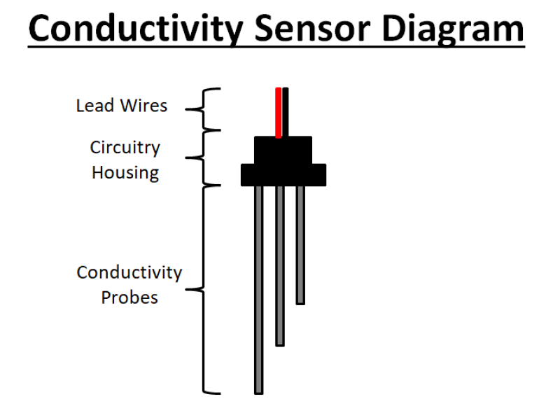
- Sensor Probes: Emerge from the container’s top or side, each forming an electrode.
- Reference Electrode (or Metallic Tank): Acts as the second electrode.
- Control Module: Supplies a small low-voltage current and monitors changes in circuit resistance. When the sensor’s measured resistance dips below a specified threshold (electrode submerged), the module triggers an output.
2.2 Example Circuit
A basic comparator circuit might treat the sensor’s electrodes as part of a voltage divider. When the electrode dips into the conductive fluid, the measured resistance significantly drops, shifting the comparator’s output from “off” to “on” (or vice versa). This logic output can drive a relay, a PLC input, or any other control device.
3. Common Use Cases
3.1 Single-Point Control
For simple high-level or low-level detection, a single electrode (plus reference) suffices. For example, to protect a pump from running dry, the sensor triggers an alarm or shuts the pump down when fluid level falls below the electrode.
3.2 Multi-Level Management
By positioning multiple electrodes at various heights, you can implement multi-threshold logic:
- Lower Electrode: Detects minimal allowable level - possibly enabling or disabling a pump.
- Upper Electrode: Signals a maximum fill level - halting pump operation or redirecting flow.
- Intermediate Electrodes (Optional): Provide additional alarm or control points.
This design is popular in water treatment plants, water towers, irrigation systems, and even certain industrial process lines.
3.3 Advantages & Considerations
- Pros:
- Affordable, straightforward design
- Low-maintenance in relatively clean water
- Reliable in many typical fluid-level applications
- Cons:
- Discrete measurement only
- Susceptible to scaling or deposits on electrodes
- Requires a minimum fluid conductivity threshold
- Risk of corrosion or electrode wear in harsh chemicals
To mitigate fouling, electrode tips are often made from corrosion-resistant materials (e.g., stainless steel) and may require periodic cleaning in heavily mineralized or contaminated fluids.
4. Implementation Tips
- Choose Proper Voltage & Control Module:
Many conductive sensors operate at low DC voltages (like 5-24 V). Using a manufacturer-provided or third-party control module ensures safe, accurate detection. - Electrode Spacing:
Make sure there’s enough gap between probes so that bridging or conduction from splashing doesn’t give false readings. - Periodic Maintenance:
In some environments, buildup on electrodes can insulate them from the fluid. Occasional cleaning can prolong reliability. - Consider Conductivity & Temperature:
Extremely pure water (e.g., distilled or deionized) won’t conduct well. If the fluid’s conductivity is uncertain, consider alternative technologies (ultrasonic, capacitive, etc.).
Conclusion
A conductive level sensor is a practical solution for detecting and controlling the level of conductive liquids in a variety of applications-from simple sump pump controls to multi-threshold industrial processes. By measuring electrical resistance between electrodes, these sensors provide straightforward on/off signals that coordinate with pumps, valves, or alarms. While they offer robust operation at an affordable cost, it’s crucial to integrate them with the right control module and ensure the liquid has adequate conductivity.
For more guidance on selecting the right water-level detection method or building a multi-level control setup, safsale.com provides expert assistance. We’re here to help you implement a dependable, cost-effective solution for your fluid management needs.