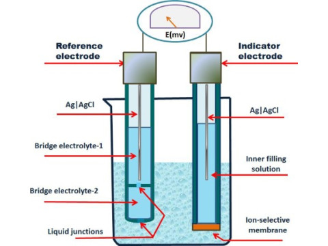
A potentiometric sensor is one of the most established and dependable measurement transducers for converting mechanical displacement into an electrical signal. Often used for position and angle detection, these sensors are prized for their simplicity, reliability, and cost-effectiveness. Below, we outline how they operate, the major types, typical performance characteristics, and the pros and cons associated with their use.
1. Principle of Operation
1.1 Voltage Divider Method
Potentiometric sensors rely on a voltage divider approach. A resistive element-often made from wire-wound or film materials-has an applied reference voltage across its endpoints. A wiper or slider (the movable contact) traverses the resistive track:
- Position Proportionality: The wiper taps a specific resistance portion, resulting in an output voltage proportional to mechanical displacement.
- Linear Response: In many designs, the output changes linearly with wiper movement, simplifying data conversion.
Because the principle is straightforward-shift the wiper, see a proportional change in voltage-these sensors do not require complex signal conditioning or advanced electronics.
1.2 Construction
- Resistive Element: Can be wire-wound (durable, stable) or film-based (potentially higher resolution).
- Wiper/Slider: A contact that moves along the resistive strip, changing the total resistance seen at the output.
- Housing/Enclosure: Protects internal parts from contaminants, though it usually incorporates an opening or rod for mechanical linkage.
2. Types of Potentiometric Sensors
2.1 Linear Potentiometers
Linear sensors measure straight-line displacement. Common in machine automation or metrology devices, they can span from a few millimeters of travel to several meters. Their rectangular or cylindrical shape accommodates a rod or slider mechanism for direct measurement.
2.2 Rotary (Angular) Potentiometers
Rotary potentiometers detect angular movement. They can range from small rotation angles-like knobs or throttle valves-to full 360° turns. Frequently found in:
- Robotics (joint position)
- Automotive controls (accelerator pedal, throttle position)
- Consumer electronics (volume knobs)
3. Key Performance Characteristics
3.1 Accuracy
Modern sensors typically offer 0.1% to 1% full-scale accuracy. Factors impacting accuracy include:
- Manufacturing Quality: Consistency of the resistive track
- Temperature Effects: Variation in resistive material behavior
- Mechanical Alignment: Wiper’s contact pressure and geometry
3.2 Resolution
Resolution refers to the smallest detectable step. Wire-wound designs have a finite step size (based on winding pitch), while film-based elements can achieve near-continuous resolution, limited by noise and wiper contact quality.
4. Major Application Areas
4.1 Industrial Automation
- Position Feedback: Monitoring cylinder strokes or the position of a robotic arm segment
- Level Sensing: Coupling a float to a linear potentiometer in some simpler system designs
- Machine Control: Adjusting setpoints in manufacturing lines
4.2 Automotive
- Pedal Position: Gas pedal or brake pedal position detection
- Throttle & Valve Control: Determining the angle of a throttle body
- Seat and Mirror Adjustments: Tracking user preferences with simple rotation/translation sensing
4.3 Robotics
Potentiometric sensors offer direct, real-time feedback for:
- Joint Angle Monitoring: In robotic arms or servo systems
- Precision Motion Systems: Low-latency analog data enabling fine control and repeated calibration
5. Pros and Cons
5.1 Advantages
- Simple, Robust Design: Few electronic components; direct voltage output
- High Reliability: Built on a proven principle with minimal electronics
- Cost-Effectiveness: Often less expensive than advanced sensors
- Linear Output (in many models): Simplifies calibration and data processing
5.2 Disadvantages
- Mechanical Wear: The wiper’s contact can degrade over time, limiting operational life
- Susceptible to Contamination: Dust or debris may affect contact quality
- Maintenance Needs: Periodic cleaning or replacement in harsh environments
- Limited Speed & Dynamic Range: Rapid or continuous friction can accelerate wear
6. Current Developments
Ongoing improvements aim to enhance material durability, reduce friction, and increase measurement accuracy:
- Advanced Resistive Films: Offering better linearity and extended lifespans
- Improved Contact Materials: Minimizing wear and ensuring stable electrical performance
- Hybrid Approaches: Combining potentiometric operation with other technologies (e.g., optical or inductive backups)
These refinements meet higher precision and longevity demands, ensuring potentiometric sensors remain a staple in modern automation, robotics, and vehicular control.
Conclusion
With their straightforward design, potentiometric sensors reliably convert linear or rotary movement into a corresponding electrical signal. From industrial machinery and robotics to automotive pedal and throttle systems, these sensors deliver cost-effective, accurate, and easily processed feedback.
While mechanical wear is an inherent limitation, ongoing advancements in resistive materials and wiper design address longevity concerns. As a result, potentiometric sensors continue to serve numerous industry applications, sustaining their place alongside more modern or digital sensing technologies.
For further guidance on selecting or integrating potentiometric sensors in your control systems, safsale.com provides expert resources, helping you balance budget constraints, accuracy demands, and environmental factors to find the best sensing solution.

