Video Intercom Systems are integral to modern residential and commercial security setups, enabling two-way audio and video communication between visitors and occupants. These systems not only enhance security by allowing visual verification of visitors but also provide convenient access control to buildings, apartments, and private homes. Understanding how video intercom systems work-including their device structure, monitor types, and locking mechanisms-is essential for selecting and maintaining an effective security solution. This guide explores the fundamental components and operational principles of video intercom systems, offering insights into their functionality and installation.
How Video Intercom Systems Work
The fundamental principle behind video intercom systems is the establishment of two-way audio and video communication between the external call panel and the internal monitor. Upon establishing a connection and assessing the situation, the homeowner can decide whether to grant access to the visitor. This decision is facilitated by the video intercom’s ability to remotely unlock the door, gate, or entrance point.
Key Components of a Video Intercom System:
External Call Device (Call Panel):
- Video Camera
- Speaker and Microphone
- Call Button
- Relay Device for Lock Control
Central Control Panel (Monitor):
- Display Screen
- Audio Communication Device
- Control Interfaces
Electric Lock (Electromechanical or Electromagnetic)
Power Supply Unit
Additionally, optional equipment such as controllers and electronic identifier readers (e.g., Touch Memory keys or Proximity cards) can be integrated to allow access without initiating a call.
1. Device Structure and Purpose of the Call Panel
a. Components of the External Call Panel:
- Video Camera: Captures the visitor's image, allowing the resident to visually verify the visitor before granting access.
- Speaker and Microphone: Facilitate two-way audio communication between the visitor and the resident.
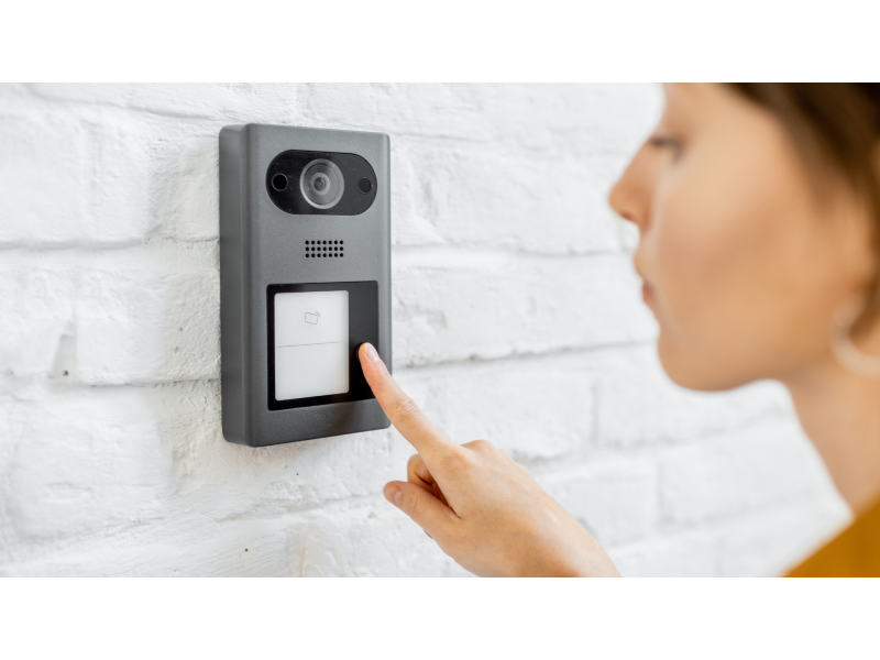
- Call Button: Initiates the communication process, alerting the resident of a visitor’s presence.
- Relay Device: Manages the electric lock by controlling the flow of power to the locking mechanism.
b. Purpose of the Call Panel:
The call panel serves as the interface between the visitor and the resident. Its primary functions include:
- Visitor Identification: Through the video camera, residents can see who is at the door.
- Communication: Enables residents to communicate with visitors without needing to physically approach the door.
- Access Control: Allows residents to remotely unlock the door, gate, or entrance after verifying the visitor’s identity.
Operational Principle:
When a visitor presses the call button, the system establishes a connection between the external call panel and the internal monitor. The resident can then see and hear the visitor, decide whether to grant access, and remotely unlock the door if desired.
2. Monitor of the Video Intercom: Types, Features, and Connection
a. Components of the Central Control Panel (Monitor):
- Display Screen (Monitor): Shows the live video feed from the external call panel. Screens can range from basic LCD displays to high-definition touchscreens.
- Audio Communication Device: Consists of speakers and microphones for two-way audio communication.
- Control Interfaces: Includes buttons or touch controls for managing functions such as unlocking doors, switching cameras, and adjusting settings.
b. Types and Features of Monitors:
Basic Monitors:
- Features: Standard LCD screen, basic audio communication, simple button controls.
- Use Case: Suitable for single-entry points where advanced features are not required.
Advanced Monitors:
- Features: High-definition displays, touchscreens, multi-channel communication, integration with other security systems.
- Use Case: Ideal for multi-entry properties, larger homes, and commercial buildings requiring enhanced security features.
Smart Monitors:
- Features: Integration with smartphones and other smart devices, remote access, cloud storage for video recordings.
- Use Case: Homes and businesses looking for comprehensive, modern security solutions with remote management capabilities.
c. Connection Methods:
- Wired Connection:
- Pros: Reliable, stable connection with minimal interference.
- Cons: Requires extensive cabling, which can be labor-intensive to install.
- Wireless Connection:
- Pros: Easier and quicker installation, flexible placement without the need for physical cables.
- Cons: Potential for signal interference and reliance on wireless network stability.
Connection Setup:
The monitor is connected to the external call panel either via wired cables (such as video signal, audio signal, power, and common ground) or through wireless protocols like WiFi or RF (Radio Frequency). Proper configuration ensures seamless communication between the external and internal units.
3. Electromechanical and Electromagnetic Locks and Their Power Sources
a. Types of Locks:
Electromechanical Locks:
- Operation: Require an electrical impulse to unlock. In their default state, they remain locked without power.
- Power Consumption: Use power only when unlocking, typically drawing several amperes during the unlock process.
- Advantages:
- Remain locked when power is lost, enhancing security.
- Can be manually overridden with a physical key or a built-in button.
- Use Case: Ideal for high-security areas where fail-safe operation is preferred.
Electromagnetic Locks:
- Operation: Remain locked as long as power is supplied. To unlock, power is removed, causing the magnetic field to release the lock.
- Power Consumption: Continuously draw power to remain locked.
- Advantages:
- Simple and quick unlocking process.
- Suitable for environments where automatic unlocking during power outages is desired.
- Use Case: Best for applications where fail-safe operation is acceptable and automatic unlocking in case of power failure is beneficial.
b. Powering the Locks:
Power Supply Requirements:
- Electromechanical Locks: Require a stable 12V or 24V power supply capable of handling high current draws during activation.
- Electromagnetic Locks: Typically operate on 12V or 24V, requiring continuous power to maintain the locked state.
Backup Power Solutions:
- Uninterruptible Power Supplies (UPS): Essential for electromagnetic locks to ensure they remain locked during power outages.
- Battery Backup: Provides temporary power to both types of locks, ensuring continued operation in the event of a power failure.
Installation Considerations:
- Wiring and Cable Sizing: Properly size cables to handle the current requirements of the locks to prevent overheating and ensure reliable operation.
- Controller Integration: Some systems may require additional controllers to manage the locking mechanisms effectively, especially when integrating with electronic access controls like biometric readers or proximity card scanners.
Operational Principle of a Video Intercom System
The operational principle of a video intercom system revolves around establishing a secure two-way communication channel between the external call panel and the internal monitor. Here’s a step-by-step overview of how it works:
- Visitor Initiates Call:
- The visitor presses the call button on the external panel, activating the system.
- Establishing Connection:
- The system establishes a live video and audio connection between the external panel and the internal monitor.
- Resident Assess and Decide:
- The resident views the visitor through the monitor and engages in conversation to assess their identity and intent.
- Granting Access:
- If the resident decides to grant access, they use the monitor’s interface to remotely unlock the door, gate, or entrance point.
- Access Control:
- The electric lock is activated, allowing the visitor to enter the premises.
Video Intercom System Components Detailed
a. External Call Device (Call Panel):
- Video Camera:
- Field of View: Determines how much area the camera can capture. A wider angle provides better coverage but may introduce image distortions.
- Image Quality: Higher resolution cameras offer clearer images for accurate identification.
- Speaker and Microphone:
- Facilitate clear two-way communication between the visitor and the resident.
- Call Button:
- Initiates the communication process, alerting the resident of a visitor’s presence.
- Relay Device:
- Controls the electric lock by managing the power flow based on the resident’s commands.
b. Central Control Panel (Monitor):
- Display Screen:
- Types: Ranges from basic LCD displays to high-definition touchscreens.
- Features: Some monitors support multiple camera inputs, allowing residents to view various entry points simultaneously.
- Audio Communication:
- Methods: Can utilize traditional handset-like buttons or modern hands-free (hand-free) audio technology.
- Control Interfaces:
- Buttons vs. Touchscreen: Traditional buttons offer tactile feedback, while touchscreens provide a more intuitive and versatile user experience.
c. Electric Locks:
- Electromagnetic Locks:
- Require constant power to remain locked. Unlocking is achieved by cutting off power.
- Electromechanical Locks:
- Remain locked without power and require a brief electrical pulse to unlock.
Powering the Locks:
- Power Sources: Typically powered by a dedicated power supply unit, ensuring that sufficient voltage and current are available for reliable operation.
- Backup Systems: Incorporate UPS or battery backups to maintain lock functionality during power outages, especially for electromagnetic locks.
d. Power Supply Unit:
- Function: Provides the necessary power to both the external call panel and the internal monitor.
- Features: Often includes surge protection to safeguard against electrical spikes and fluctuations.
e. Additional Equipment:
- Controllers: Manage the interaction between multiple intercom units and integrate with other security systems.
- Electronic Identifier Readers: Allow access via electronic keys (Touch Memory) or proximity cards, enhancing security and convenience.
Integration with Multi-Unit Buildings
For multi-unit buildings like apartment complexes or office buildings, video intercom systems become more complex due to the need to manage multiple entry points and user interfaces. Here’s how they operate:
a. Call Panel Configuration:
- Individual Call Buttons: Each apartment or office unit is assigned a unique call button.
- Shared Panels: Centralized panels on each floor or entry point manage multiple calls.
b. Switchboards (Commute Stations):
- Function: Act as intermediaries that route calls from the external panels to the appropriate internal monitors.
- Placement: Typically installed on stairwells or common areas.
- Connection: Linked to a central control unit that manages call routing and lock control for all units.
c. Operational Workflow:
- Visitor Calls a Specific Unit:
- The visitor selects the desired apartment or office number on the call panel.
- Signal Routing:
- The call signal is sent to the switchboard, which then forwards it to the corresponding internal monitor.
- Resident Interaction:
- The resident views and communicates with the visitor through their monitor.
- Access Control:
- Upon approval, the resident unlocks their specific door remotely.
Technical Challenges:
- Cabling Requirements: Extensive wiring is needed to connect multiple external panels to the central switchboard.
- Space Constraints: Installing additional lines through existing structures can be technically challenging and costly.
Solution: Coordinate Matrix Video Intercoms
- Principle: Use a matrix switching system that allows efficient routing of multiple calls through a centralized switchboard without the need for individual wiring for each unit.
- Benefits: Reduces the complexity and cost associated with wiring, especially in buildings with numerous units.
Installation and Connection of Video Intercom Systems
Proper installation and connection of video intercom systems are crucial to ensure their effective and secure operation. Below are detailed guidelines for installing video intercoms, connecting to existing systems, and best practices to ensure system safety and reliability.
1. Installation of Intercom Components
a. Installing the External Call Panel
Steps:
Choose the Optimal Location:
- Select a location near the main entrance or gate for easy access by visitors.
- Ensure the external panel is mounted at a convenient height, typically between 4.5 to 5.5 feet from the ground, to accommodate both adults and children.
Mounting the Call Panel:
- Secure the panel to a sturdy surface using tamper-proof screws and brackets to prevent unauthorized removal.
- Attach the protective hood to shield the panel from weather elements like rain, snow, and direct sunlight.
Connecting to Power Supply:
- If the system requires external power, connect the call panel to a stable power source using the provided adapter.
- For systems with built-in batteries, ensure the batteries are properly installed and charged.
Network Connection:
- Connect the external panel to the local network using an Ethernet cable if required.
- Configure the network settings according to the manufacturer’s instructions to ensure proper communication with the internal unit and other networked devices.
b. Installing the Central Control Panel (Monitor)
Steps:
Determine the Ideal Location:
- Position the monitor in a central area of the home, such as the living room or near the main entrance, for easy access and visibility.
- Ensure the unit is at a comfortable viewing height, typically between 4 to 5 feet from the floor.
Mounting the Internal Panel:
- Secure the panel to the wall using screws, ensuring it is level and easily accessible.
- Conceal any necessary cables using cable clips or conduits to maintain a clean appearance.
Connecting to Power and Network:
- Connect the internal unit to the power supply and local network according to the installation manual.
- For wireless systems, ensure the internal unit is properly paired with the external call panel and connected to the network.
Integrating with Locking Devices:
- Connect the intercom system to the electromagnetic or electromechanical locks following the specific wiring instructions provided by the manufacturer.
- Test the lock operation to ensure seamless integration with the intercom commands.
2. Connecting to Existing Systems
If your property already has an existing intercom or access control system, integrating your new video intercom requires careful planning and consideration.
Steps for Integration:
Determine System Compatibility:
- Identify the type of existing system (analog, digital, wireless) and ensure the new intercom system is compatible.
- Consult with the existing system’s manufacturer or a professional installer for integration guidelines.
Consult with the Service Provider:
- Contact the company responsible for the existing intercom system to discuss compatibility and integration options.
- Obtain necessary permissions and technical support for seamless integration.
Wiring Considerations:
- Use compatible wiring standards and protocols to connect the new intercom to the existing system.
- Avoid mixing different communication standards to prevent signal interference and system malfunctions.
Configuration and Programming:
- Program the new intercom unit to recognize and communicate with the existing system’s controller.
- Test the integration to ensure proper functionality and seamless operation.
Troubleshooting:
- Address any issues related to signal interference, alignment, or communication between units.
- Seek professional assistance if integration challenges arise.
3. Best Practices for Installation
Professional Installation:
- While DIY installation is possible for simple systems, hiring certified professionals ensures precise alignment, secure mounting, and proper wiring.
- Professionals can also provide valuable insights and recommendations tailored to your specific security needs.
Regular Maintenance:
- Schedule routine inspections of the intercom system to identify and address any wear, alignment issues, or electrical problems.
- Clean and lubricate mechanical parts to maintain smooth operation.
Secure Wiring:
- Route cables through concealed pathways to protect them from physical damage and unauthorized access.
- Use high-quality, durable cables that can withstand environmental factors and prevent voltage drops over long distances.
Backup Power Solutions:
- Implement Uninterruptible Power Supplies (UPS) or battery backups to maintain intercom functionality during power outages.
- Ensure backup power can sustain the intercom system for the required duration to allow safe evacuation.
Compliance with Standards:
- Follow the National Electrical Code (NEC) and other relevant standards during installation to ensure safety and compliance.
- Integrate the intercom system with fire alarm systems to facilitate safe evacuation during emergencies.
Electromechanical and Electromagnetic Locks: Functionality and Powering
Locks are a critical component of any video intercom system, determining the security and access control of the premises. Understanding the differences between electromechanical and electromagnetic locks, as well as their power requirements, is essential for effective system implementation.
1. Electromechanical Locks
Functionality:
- Operation: Electromechanical locks require an electrical impulse to unlock. In their default state, they remain locked without power.
- Unlocking Mechanism: A brief electrical pulse activates the solenoid or motor, causing the lock to release and allowing the door to open.
Powering Electromechanical Locks:
- Power Supply: Typically operate on 12V or 24V DC, requiring a stable power source.
- Current Requirements: Can draw several amperes during activation, necessitating appropriate cable sizing to handle the load.
- Wiring Considerations: Ensure that wiring is capable of handling the high current without overheating. Use wires with sufficient gauge to match the lock's current draw.
Advantages:
- Fail-Secure Operation: Remain locked when power is lost, enhancing security during power outages.
- Manual Override: Can be opened manually with a physical key or an integrated manual release button.
Use Cases:
- High-Security Areas: Suitable for environments where fail-secure operation is preferred, such as apartment entrances and office buildings.
- Residential Applications: Ideal for homes requiring reliable and secure access control.
2. Electromagnetic Locks
Functionality:
- Operation: Electromagnetic locks remain locked as long as power is supplied. To unlock, power is removed, causing the magnetic field to release the lock.
Powering Electromagnetic Locks:
- Power Supply: Operate on 12V or 24V DC, requiring a continuous power supply to maintain the locked state.
- Current Requirements: Continuously draw power to stay locked, but typically have lower current spikes compared to electromechanical locks.
- Wiring Considerations: Ensure that wiring is secure and capable of handling continuous power without degradation.
Advantages:
- Fail-Safe Operation: Automatically unlock during power outages, allowing for emergency exits without manual intervention.
- Simpler Installation: Generally easier to install with fewer moving parts compared to electromechanical locks.
Use Cases:
- Emergency Exits: Ideal for doors that require quick and easy access during emergencies, such as fire exits.
- Low-Security Areas: Suitable for environments where automatic unlocking is beneficial, and fail-safe operation is acceptable.
3. Powering and Backup Solutions
Power Supply Requirements:
- Dedicated Power Sources: Both lock types often require dedicated power sources to ensure reliable operation.
- Voltage Stability: Maintain a stable voltage to prevent lock malfunctions or security breaches.
Backup Power Solutions:
- Uninterruptible Power Supplies (UPS): Essential for electromagnetic locks to ensure they remain locked during power outages, preventing unauthorized access.
- Battery Backups: Provide temporary power to both lock types, ensuring continued functionality when the main power source is disrupted.
Installation Tips:
- Proper Sizing: Accurately calculate the power requirements for each lock type to select appropriate power supplies and backup solutions.
- Secure Connections: Ensure all electrical connections are secure and protected against tampering and environmental factors.
- Compliance: Adhere to local electrical codes and standards when installing and wiring locks to ensure safety and legality.
Final Thoughts
Video Intercom Systems are pivotal in enhancing the security and convenience of residential and commercial properties. By understanding the operational principles, device structures, monitor types, and locking mechanisms, you can make informed decisions when selecting and installing a video intercom system that best fits your security needs. Whether opting for electromechanical or electromagnetic locks, integrating these components with advanced video intercom technology ensures robust protection and seamless access management for your premises.
Key Takeaways:
Understand the Components: Familiarize yourself with the main components of video intercom systems, including the external call panel, central monitor, electric locks, and power supply units.
Choose the Right Lock Type: Decide between electromechanical and electromagnetic locks based on your security requirements and the desired fail-safe or fail-secure operations.
Ensure Proper Installation: Follow best practices for mounting, wiring, and configuring your intercom system to achieve optimal performance and security.
Implement Backup Power Solutions: Utilize UPS or battery backups to maintain intercom functionality during power outages, ensuring continuous security.
Regular Maintenance: Conduct routine inspections and maintenance to prevent wear and ensure reliable operation of both intercoms and locking devices.
Manage Access Effectively: Regularly update access credentials and manage user permissions through the controller to maintain security integrity.
Integrate with Other Security Measures: Combine intercoms with surveillance cameras, alarm systems, and access control systems for comprehensive protection.
Adhere to Standards: Ensure all installations comply with relevant electrical and building codes to guarantee safety and legal compliance.
Secure Wiring Practices: Route cables through concealed pathways and protect them from physical damage and tampering.
Professional Assistance: Consider hiring certified security professionals for installation and maintenance to ensure intercom systems operate effectively and securely.
For expert assistance in selecting and installing video intercom systems, ensuring compliance with relevant standards, or accessing comprehensive project documentation, visit safsale.com. Our specialists are ready to help you design and deploy reliable, compliant, and efficient access control solutions tailored to your specific security needs.
Important Notice on Standards
All referenced documents and standards in this guide are provided for informational purposes only and should not be used as official publications. For authoritative guidelines and legal requirements, always consult the official standards organizations or regulatory bodies.