


Moving a camera or changing its mounting position can leave an otherwise useful cable a few feet short. Extending the run may be practical, but every connection adds a possible failure point. The right method depends on whether the system uses coaxial video cable, Ethernet cable, or a combined cable carrying video and separate low-voltage power.
For a permanent installation, one continuous cable is usually the cleanest solution. When replacing the entire run is impractical, use connectors designed for the cable and signal, protect the joint, and test the finished system. No splice can promise zero signal loss under every condition.
Extending coaxial camera cable
Coax has a center conductor, dielectric insulation, an outer shield, and a protective jacket. CCTV video connections generally require 75-ohm components. The connector must fit the cable diameter, dielectric, shield construction, and center conductor. A physically similar connector is not automatically suitable.
Solid-center coax
- Turn off the camera and any power carried on the cable before working. Cut back damaged or corroded cable and prepare both ends to the connector manufacturer's stripping dimensions.
- Fit compatible 75-ohm BNC connectors and join them with a 75-ohm female-to-female BNC coupler. Keep shield strands away from the center contact.
- Where the equipment and cable system use F connectors, select matching connectors and a suitable barrel coupler. Some designs use the solid center conductor as the contact. Compression and crimp versions need the correct tools; do not assume all F connectors are tool-free.
- Provide strain relief so the coupler does not carry the weight of the cable.
Stranded-center coax and combined camera cable
For stranded coax, use connectors specifically approved for stranded center conductors. Do not turn a stranded conductor into a makeshift solid pin by coating it with solder unless the connector instructions expressly call for that termination. Excess heat, unsuitable flux, or a poorly fitted connector can damage insulation and create an unreliable connection.
Combined, or siamese, camera cable typically includes a coaxial video section and separate power conductors. Extend the video section with the appropriate coax connectors. Join the power conductors separately with connectors rated for their wire size, current, and environment. Verify polarity against the equipment markings; jacket colors alone are not proof of polarity. A terminal block can serve a suitable power circuit, but it does not preserve the impedance of a coaxial video connection.
Simply twisting exposed wires together is not a permanent repair. Movement, oxidation, and loss of shielding can cause intermittent pictures, interference, or power failure. A picture that looks normal during a quick test does not establish long-term reliability.
Protecting an outdoor connection
Place the joint in a suitable weather-resistant enclosure with correctly sized cable glands and strain relief. Follow the enclosure's mounting and sealing instructions. Arrange cable entries to reduce water entry and allow the intended drainage or condensation management.
Heat-shrink tubing shrinks when deliberately heated during installation, not as a dependable response to outdoor temperature changes. Adhesive-lined tubing may be appropriate for a specified splice, but it does not make every connector waterproof. Ordinary hot glue and an enclosure filled with arbitrary sealant are not substitutes for an approved outdoor connection system. Some compounds attack plastics, trap moisture, or prevent future servicing.
Extending Ethernet cable for an IP camera
Use a category-rated inline coupler or termination module compatible with the installed cable and PoE requirements. Properly terminate both ends, maintain pair twists close to the contacts, and keep the same wiring scheme throughout. A passive RJ45 coupler joins two cables; it does not regenerate the Ethernet signal or extend the channel's rated distance.
For ordinary copper Ethernet, plan around a maximum 100-meter channel, approximately 328 feet, including patch cords. If the completed run would exceed the equipment's supported distance, use an appropriate active extender, an intermediate switch with power, or fiber with powered equipment at the far end. Verify the complete design rather than assuming another connector solves the distance problem.
Do not splice Ethernet conductors by hand-twisting them, even for a temporary camera installation. A connection can pass a basic continuity check while failing under network traffic or PoE load.
Choose the cable material and verify the result
Four-pair Cat5e or Cat6 cable with copper conductors is a practical starting point for many camera networks. Copper-clad aluminum is not equivalent to solid copper, particularly where power must travel along the cable. Select the jacket for the actual indoor, outdoor, wet-location, or building-space conditions. A 1,000-foot bulk box is a supply length, not permission to build a 1,000-foot passive Ethernet link.
After installation, test wire mapping or the coax connection, confirm the camera's image, and check operation with night illumination and other power-hungry features enabled. Watch for reboots and dropped video. For Ethernet, use appropriate qualification or certification testing when required; for separate DC power, check voltage at the camera under load.
Compare compatible security cameras at Safsale and plan the cable, connectors, and power system together.
Related products from Safsale
Continue from Academy guidance to live equipment and components available on Safsale.
 Alpha RAP-2150-500 500 Meter Roll of 2 Conductor CableView product
 Windy City/Smart Wire 659116DB-500 Siamese Type RG 59/U Non-Plenum, Direct Burial Cable, 500ftView product
 Alpha CB-7004 1000 ft. 4-Pair 22AWG 7000 Series WireView product
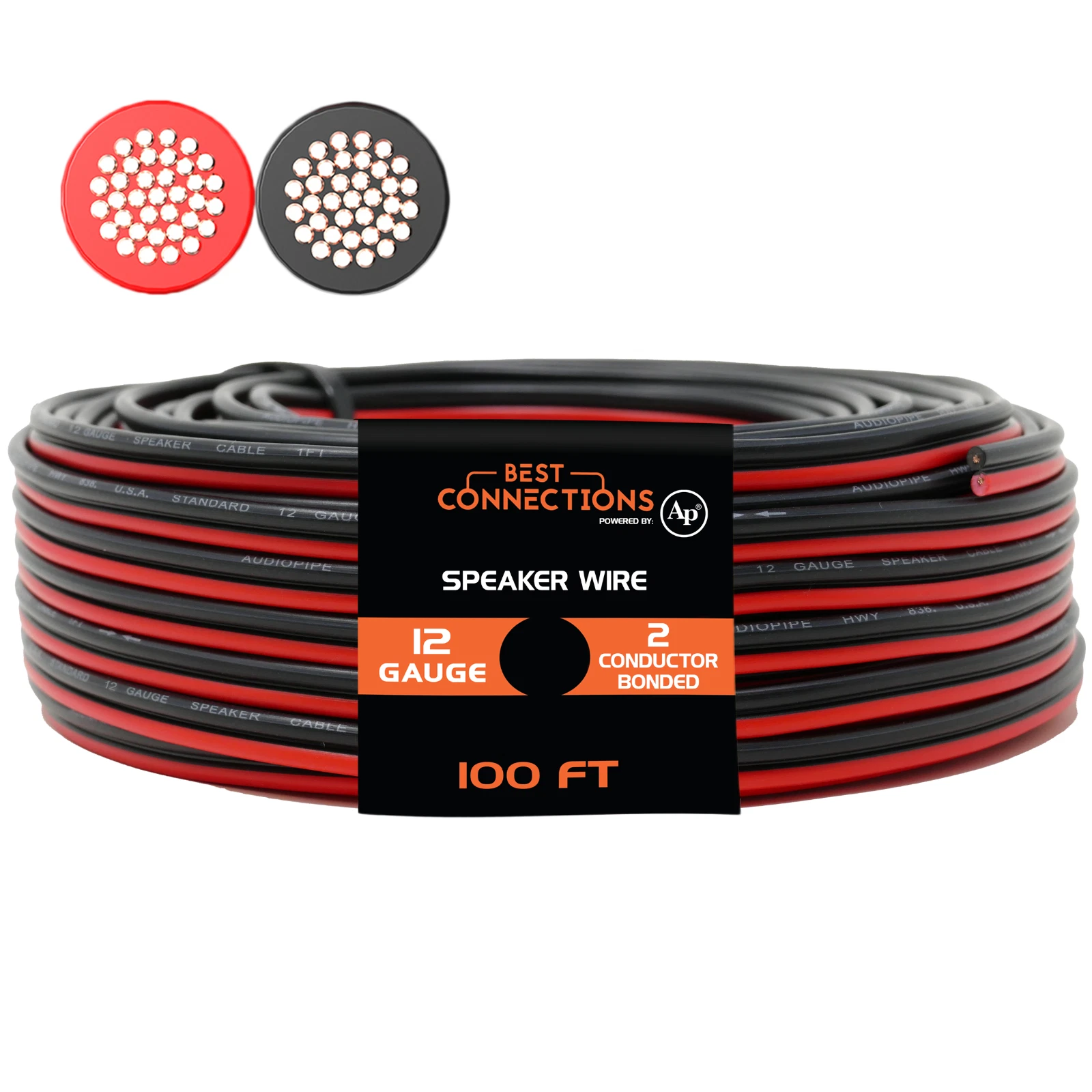 Alpha RAP-2150 100 Meter Roll of 2 Conductor CableView product